4.2.7.1. PLC X Relay (External Input)
4.2.7.1. PLC X Relay (External Input)
This displays the state of the signals inputted through the standard/extension IO board and the state of the input signals of DeviceNet master.
On the manual or auto mode initial screen, select『[F1]: Service』 → 『1: Monitoring』→『7: PLC relay data』→『1: PLC X Relay (external input)』.
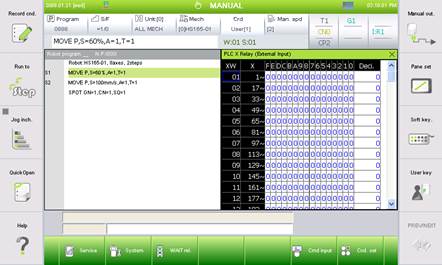
Figure 4.25 PLC X Relay (External Input)

l Pressing the [F1: Node state] button allows verification of the activation status of the embedded field bus of the selected node number (Green background: Activated. Red background: Not activated).
l When the [F2: Physical value] button is pressed, the physical input/output state before the logic of the relevant signal is actualized will be displayed. For example, when the signal FN1.5 is negative logic and the actual signal is not actually inputted, the basic monitoring screen will display that the value of the relevant signal is being inputted. However, if the [F2: Physical value] button is pressed, a no-input state will be displayed because no signal is actually inputted.
l Pressing the [F3: X/Y] button will allow verification of the current input and output of the current node while modifying them.
l Pressing the [F4: Find] button will bring up a dialog box that will allow a search for the page where signals exist. Enter the desired signal into the dialog box. For example, in order to find the FN20.3 signal, you just need to enter “20.3”
l Every time the [F5: Display type] button is pressed, the displayed data format will change as the following.
Byte type (XB) -> word type (XW) -> long type (XL) -> byte type (XB)
l Pressing the [F6: Prev FN]/ [F7: Next FN] button will allow movement to the next node that is currently connected.