4.2. Monitoring
4.2. Monitoring
This function displays the condition of various data inside the controller.
On the initial screen, enter『[F1]: Service』 → 『1: Monitoring』to display the following submenus.
The items that can be monitored will vary depending on the controller setting. The following figure displays all items that can be monitored.
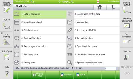
Figure 4.2 Monitoring Items 1
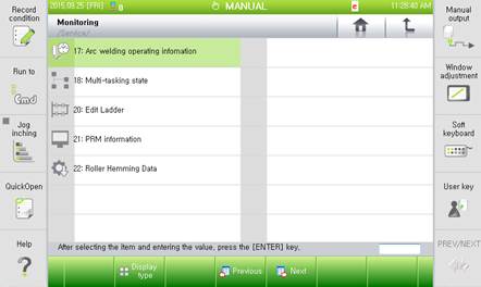
Figure 4.3 Monitoring Items 2

l For more details, refer to “2.2.2.3 Window control function” section of the Hi5 operations manual for window (TP screen) split function.
The following shows the items that can be monitored depending on the controller setting.
(1) Data of each axis: All settings
(2) Input/output signal: All settings
(3) Field bus signal: All settings
(4) Spot welding data: Valid spot welding setting
(5) Sensor synchronization: Conveyor / press setting
(6) PLC relay data: All settings
(7) Analog data: All settings
(8) Cooperation control data: Valid cooperation control setting
(9) Various data: All settings
(10) Work program data Hot Edit: All settings
(11) Arc welding data: Arc welding valid setting
(12) Operating information: All settings
(13) Embedded field bus node state: All settings
(14) System property data: Engineer mode
(15) Arc welding operating data: Valid arc welding setting
(16) Multi-tasking state: All settings
(17) Servo tool change: Valid servo tool change setting
(18) Ladder edit: All settings
(19) Roller hemming data: Valid roller hemming squeeze control setting
(20) Force sensor: Valid force control setting
(21) Playback speed automatic adjustment state: Enables automatic adjustment of the playback speed
4.2.8. Cooperation control data
4.2.13. Embedded field bus node state
4.2.14. System characteristic data