3.6.2. CalibTab
3.6.2. CalibTab
This mode executes the camera calibration to align the image coordinate and camera coordinate. “HRVision Press” executes the calibration using the following calibration board.
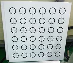
The 1000mmx1000mm calibration board contains the arrangement of circles of diameter 100mm, which are spaced 170mm apart. Thin solid lines are crossed through the center of each circle. The calibration points are used for calibration. Referring to Table 1, the three points are randomly selected on the circles in the calibration board in accordance with the vision work environment and/or coordinate direction and they define the positions of the points by P1, P2, and P3 as well as the measure, the enter image coordinate system, and the robot coordinate system for P1, P2 and P3 points.
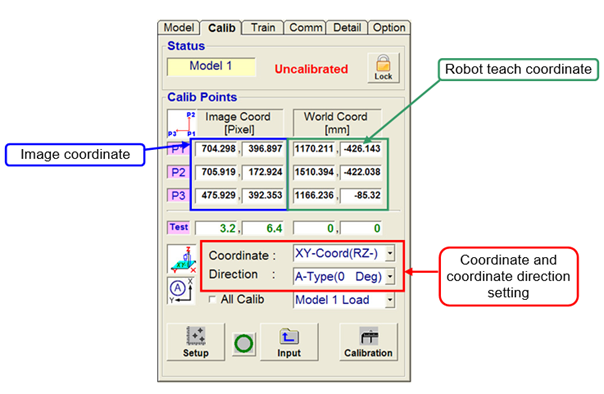
The detail description of “Calib” tab is as follows.
n Status : It displays the model, whether there is calibration etc.
- Model: It displays the model executing the calibration.
- Calibration condition:
It display whether the calibration is executed or not as shown below.
Condition | Screen | Description |
Before calibration |
| Calibration is not executed. |
After calibration |
| Calibration is executed. |


-  Lock button: This locks all buttons related to calibration.
n Calib Points
Enter the image coordinate and robot teach data for the Calibration Points.
The positions of calibration points in the image coordinates can be configured either through performing pattern recognition by clicking the "Setup" button, or performing elliptical fitting by clicking the  button. The positions of calibration points in the robot coordinates system can be configured through directly inputting positions of calibration points. Note that the inputted coordinates are subject to selected "Coordinate".
Enter the image coordinate and robots teach data for the Calibration Points.
n Test
When calibration has been performed, the position of the current mouse point based on the image coordinates and the robot coordinates system will be displayed.
n Coordinate
Configure robot coordinates system according to the camera operation condition.
There are 6 configurable coordinates systems are available according to camera operation conditions (installation and orientation direction).

n Direction
Setup the coordinate axis direction of calibration.
When you select the combo box, the direction changes to fit the coordinate axis direction of the selected picture of the status window.

※ Refer to Table 1 to set the “Coordinate” and “Direction” for each work environment.
※Generally, XY-Coord (RX-) coordinate system is applied to the press centering vision system for which a camera is fixed at the top of the robot workspace. Any of the A–D types shall be applied to the “direction” depending on the direction of camera arrangements.
<Setting coordinate system and direction of camera orientation according to the operating environment>
Camera operation condition | Setting positions of image-based robot coordinates system and calibration points | Direction of camera orientation | ||||
A-Type | B-Type | C-Type | D-Type | |||
|
|
|
| |||
XY-Coord (RZ-) |
| Robot coordinates system |
|
|
|
|
Setting positions of calibration points |
|
|
|
| ||
XY-Coord (RZ+) |
| Robot coordinates system |
|
|
|
|
Setting positions of calibration points |
|
|
|
| ||
YZ-Coord (RX-) |
| Robot coordinates system |
|
|
|
|
Setting positions of calibration points |
|
|
|
| ||
YZ-Coord (RX+) |
| Robot coordinates system |
|
|
|
|
Setting positions of calibration points |
|
|
|
| ||
ZX-Coord (RY-) |
| Robot coordinates system |
|
|
|
|
Setting positions of calibration points |
|
|
|
| ||
ZX-Coord (RY+) |
| Robot coordinates system |
|
|
|
|
Setting positions of calibration points |
|
|
|
| ||


n All Calib
When you select check the checkbox, the same calibration data is applied to all the models.
When you uncheck the checkbox, you can copy specific calibration data or calibrate applicable models separately.
n Setup
This button is of toggle type:
Clicking it once enables "Search", and clicking it for the second time enables "Setup".
If you click the "Setup" button, 3 search windows and coordinate axes of search windows will be displayed.
Arrange the 3 search windows properly so that 3 calibration points can be recognized, and place each coordinate axis on the center of each calibration point. For detailed description, refer to "4.4.2.4.1 Method of Calibration Pattern Recognition".
When the arrangement of each search window and coordinate axis is completed, click on the “Search” button.
If the search process fails, the failed calibration point is provided as output in the following window. Retry the “setup” and “search” process so that the failed calibration point can be easily distinguished.

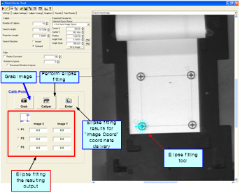
n 
This is the method of measuring a circle center, which exists on the calibration board, based on elliptical fitting. Place the elliptical fitting tool on the points of P1, P2, and P3 that are set based on the "Coordinate" and "Direction" information selected in the "Calib" tab, and click the "Caliper" button. For detailed description, refer to "4.4.2.4.2 Method of Elliptical Fitting".
n Input
When you have directly entered the calibration points or copied specific calibration data, it functions as data entry to the actual memory to execute the calibration.
n Calibration
When the image coordinate and robot coordinate of calibration points are entered, click on this button to execute the camera calibration. If the RMS value of executed calibration is lower than the “RMS Error Limit”, the following window is provided and the camera calibration is completed. Refer to 3.7.5 Detail tab for ”RMS error limit” setup.

If the RMS error is higher than the “RMS Error Limit”, the following warning window is generated. Reset the image coordinate and robot coordinate to execute the calibration again.
