7.4.1. The basic way to create steps
7.4.1. The basic way to create steps
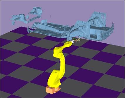
Let’s assume that there is data for the following robot and chassis floor, and create some steps at a part of edge.
Click on『Step Creation/ Modification』 button on the Standard tool bar.

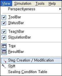
Or you can select『View – Step Creation/ Modification』 from the main menu.
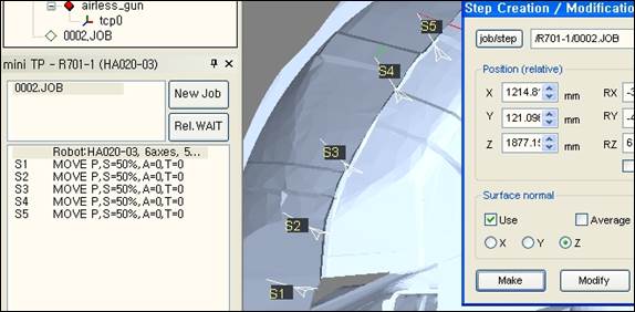
The following “step creation/ modification” dialog box appears.
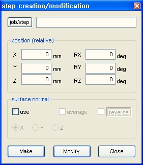
You must set at which job you want to create the step through the edit window on the right side of the “jop/step” button. You can either directly enter the T path through the keyboard or press the “jop/step” button and click on the job from the tree window.

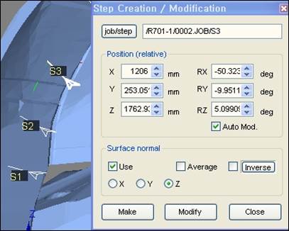
Click on the surface location of the chassis floor data to create the step. When the job is set in the “Step Creation/ Modification” window, the coordinate appears on the clicked surface. This coordinate is only to show the location and it has not created the step yet.
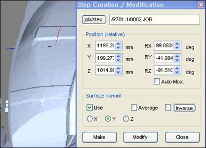
When the location is incorrect, click again and to adjust the direction, enter the rotation angle in the edit window of RX, RY and RZ.
(When you turn the mouse wheel after clicking on the wanted edit window, it increases/decreases by 10 degrees.)
(Location value, that is the value of X, Y and Z in the edit window can be directly edited with the keyboard or mouse wheel.)
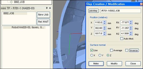
If you want to create a step so that the specific axis is vertical to the surface automatically, select the use check box of surface normal and select X, Y or Z.
When you click on the surface in this condition, you can see the step indicated with the selected axis vertical to the surface.
If you want to change the direction of the vertical axis by 180 degrees, press the Inverse button.
(If you want to continuously apply the inverse direction, check the Inverse check box.)
Set the parameter of the step to create in the teach bar.
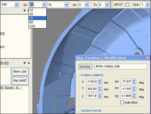
Now, click on the create button to create a new step at the end of the designated job.
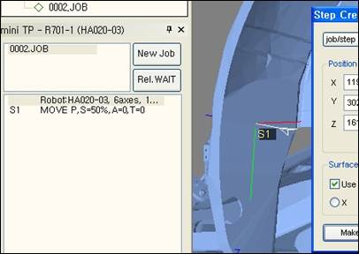
Try creating other steps on the surface of the chassis floor with the same method.
Steps that are displayed in red mean the robot can’t do this pose. In order to modify this, press iob/step button, click the steps in red on 3-D space, to enter T path in the dialog box.
(Or you can directly enter with the keyboard.)
Now, click on a new location and click Modify button. Or if you adjust the spin control of a location edit box (it’s convenient if you use a wheel on a mouse) after checking Auto Mod. check box, then you can easily find the location that is changed to white because the step location is immediately changed.
(The edit only affects location/direction. The set parameter value of the current step of the teach bar is not applied.)