7.5. Import teach point and location group
7.5. Import teach point and location group
You can set up the direction to be vertical to the surface of an object by importing mass teach location data from CAD data. (It’s only available for data exported from CATIA V5.)
And steps also can be distributed properly by using a mouse when the work should be done by several robots.
First, below is how to extract welding points in CATIA V5.
Hide parts except welding points.
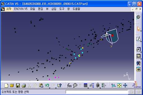
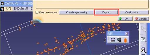
Select Measure Inertia/Customize...

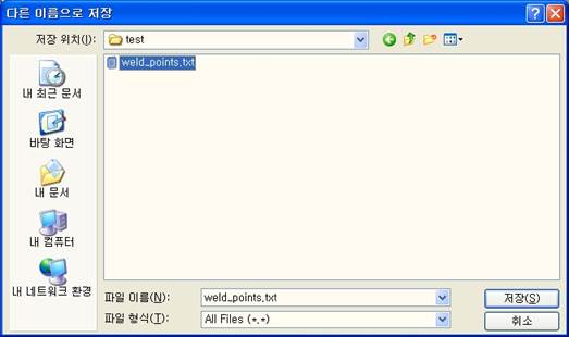
Drag the whole welding point area, click Export button, and select a file name.
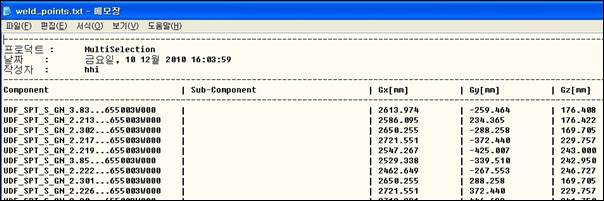
It generates a text file as below. (Only X, Y, and Z teach locations are extracted.)
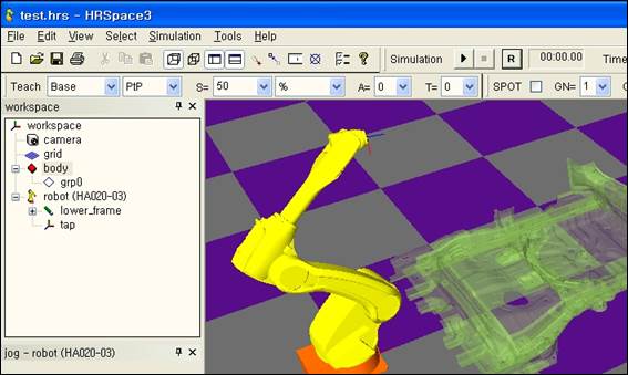
Suppose there’re work space that has a robot and a body shape comes from CATIA.
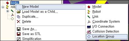
Click the right mouse button on the body and create a new location group.
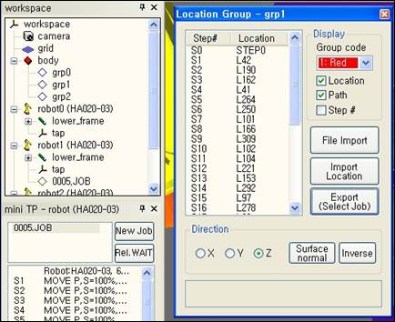
Assign a name to the created group, open popup menu, and click Location Group Properties…

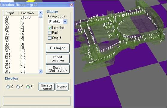
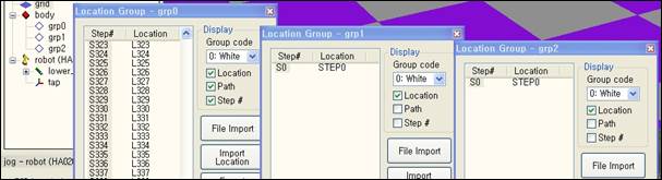
Location Group Properties dialog box is open as below.
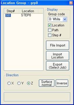
First, click [File import] button, select CATIA file type, and specify teach location data that are prepared.

Teach locations are created on the body as below. The teach location model that is created with this method is called Location and its set is called Location group. Locations and Step look very similar but Location only has location/direction/order and doesn’t include various parameters and functions.
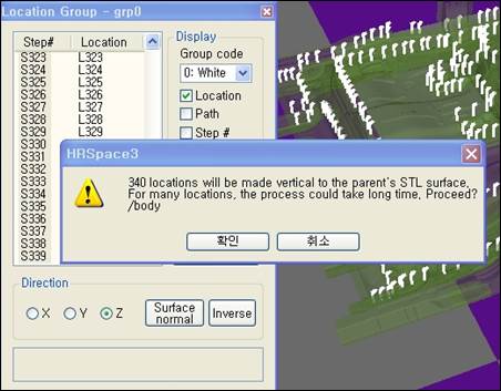
Data exported from CATIA only has teach location and doesn’t have direction. If you want to make locations be vertical to the surface of parents’ body, select locations that you want to modify and click [Surface normal] button. (You can click step # from Step # in the left box of the dialog box or select it from a 3-D screen. Use [SHIFT] key or [CTRL] key together to select several locations at a time.) You can adjust the axis to be verticalized if you select a radio button for X, Y, or Z in advance.
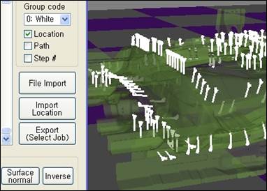
Below is the result after verticalizing. Since the parents of location grp0 are a body, surface of the body is used as a base. If directions of some locations are inversed, you can inverse them by selecting them and clicking [Inverse] button.
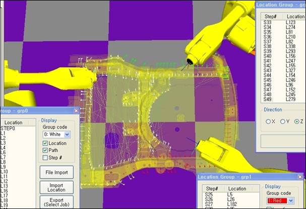
You can also display path and step # if you check the check boxes for them of Display group in Location Group dialog box.
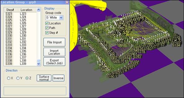
In the picture as above, the locations are widely distributed and the order is very complicated for one robot to do the work. Let’s distribute the work to 3 robots and make the order better to do the work.
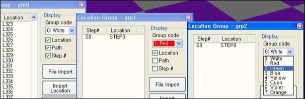
Add 2 location groups as children to the body and open Location Properties dialog box for each group.
Use different colors to distinguish the two groups.
Click [Import Location] button from grp1 dialog box and drag target locations on a 3-D screen by keeping pressing the left mouse button. Locations in white have been changed to red and a path is created according to the order that is dragged. You can see target locations in grp0 list box are moved to grp1 list box.
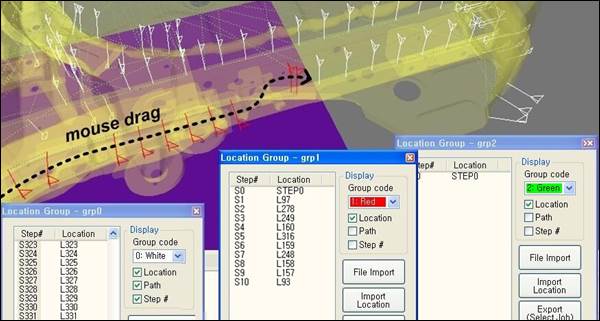
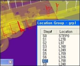
If you select one location from the list box or on the 3-D screen and drag it, it is inserted to the next location that you select. By applying this, locations that are already moved to grp1 can be reordered by dragging them again.
Parts of grp0 locations are moved to grp2 also in the same way.
If you click [Export (Select Job)] from the dialog box and select an empty JOB program from tree window, locations are created by JOB steps that are selected.