5.9.2.7. CAN Communications Connector CANS1, CANS2
5.9.2.7. CAN Communications Connector: CANS1, CANS2
Data communication with the MAIN board uses the CAN of Half Duplex method. Bottom modules of the controller are configured for CAN data communication using a Daisy Chain method. Therefore, there are two CAN connectors on the board. Figure 5.66 below describes the CAN connector exterior and pin allocation. Even though you can connect the power through #6 (VCC-DC5V) and #2 (VCC Ground) to the board, it is recommended to use the CNP1 power connector.
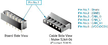
Figure 5.70 Method of Connecting CAN Connector on Analog Board (BD584)
Table 5‑39 Pin Configuration of CAN Connector on Analog Board (BD584)
Number | Name | Use | Remarks |
1 | Shield | Connect shield of CAN cable |
|
2 | DC5V GND | Connect board power DC5V ground (Recommended to connect through CNP1) |
|
3 | CAN_G | Connect ground for CAN communication |
|
4 | CAN_L1 | Connect L signal of CAN communication |
|
5 | CAN_H1 | Connect H signal of CAN communication |
|
6 | DC5V | Connect board power DC5V ground (Recommended to connect through CNP1) |
|
When connecting several boards, the terminating resistance must be processed precisely. CAN data communication uses the Daisy Chaining method. For this reason, only the board connecting the CAN communication cable at the end must be connected to the terminating resistance; all other boards must not be connected to the terminating resistance. For the connection of the terminating resistance, use the JP1 jumper next to CANS connectors 1 and 2. When you short-circuit JP1, the terminating resistance is connected, and when opened, the terminating resistance is disconnected.