5.9.2.3. Analog Input
5.9.2.3. Analog Input
The board can receive analog voltage input of 8 channels. Each channel has 12-bit resolving power in the range of -12V~+12V. The input impedance is 20kΩ, and output impedance of the connected device should ideally be infinite. As the analog value of all 8 channels is transmitted to the MAIN board every 1msec, the scan time is 1msec.
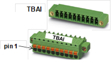
Figure 5.64 Terminal Block for Analog Input on Analog Board (BD584)
The pin allocation of terminal block TBAI for analog input is shown in the following Table.
Table 5‑36 Pin Configuration of Analog Input Terminal Block (TBAI) on Analog Board (BD584)
Number | Name | Use | Remarks |
1 | AIN1 | Analog Input Channel 1 |
|
2 | AIN 2 | Analog Input Channel 2 |
|
3 | AIN 3 | Analog Input Channel 3 |
|
4 | AIN 4 | Analog Input Channel 4 |
|
5 | AIN 5 | Analog Input Channel 5 |
|
6 | AIN 6 | Analog Input Channel 6 |
|
7 | AIN 7 | Analog Input Channel 7 |
|
8 | AIN 8 | Analog Input Channel 8 |
|
9 | AING | Analog Input Ground |
|
10 | AING | Analog Input Ground |
|
The method of connecting the analog input port is shown in Figure 5.61 below. This example shows the method of connecting 5 analog signals. Each signal sends input to AIN1~AIN5, and the ground is connected to AING pin #9 or #10. The input signal is AD converted through the signal control circuit inside the board. The power used in the analog input circuit uses the insulation separated type DC/DC converter, and is separated from the internal power of the controller.
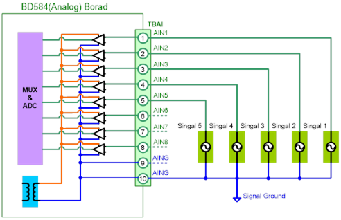
Figure 5.65 Method for Connecting Analog Input on Analog Board (BD584)