5.9.2.2. Digital Output
5.9.2.2. Digital Output
The board has 8 digital output ports that can output ON/OFF. These are electrically insulated from the external device using the photo MOSFET. To expand the applied scope, each input can select and use common output signal and individual contact point output of two types.
Maxim3um permitted current of unit output is 125mA at 24V voltage. Therefore, when all 8 of the outputs are used, the total current consumption is about 1000mA.
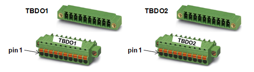
Figure 5.61 Terminal Block for Digital Output on Analog Board (BD584)
Use assigned output to connect the arc welder. Details are shown in Table 5-26 below.
Table 5‑34 Pin Configuration of Digital Output Terminal Block (TBD01) on Analog Board (BD584)
Number | Name | Name for Arc Welder Connection | Remarks |
TBDO1 1 | DOUT 1 | TORCH_SW |
|
TBDO1 2 | DOUT 1 COM |
|
|
TBDO1 3 | DOUT 2 | INCHING |
|
TBDO1 4 | DOUT 2 COM |
|
|
TBDO1 5 | DOUT 3 | RETRACT |
|
TBDO1 6 | DOUT 3 COM |
|
|
TBDO1 7 | DOUT 4 | STICK_CHECK |
|
TBDO1 8 | DOUT 4 COM |
|
|
TBDO1 9 | DO_COM1 | Signal Common 1 |
|
TBDO1 10 | DO_COM2 | Signal Common 2 |
|
Table 5‑35 Pin Configuration of Digital Output Terminal Block (TBD02) on Analog Board (BD584)
Number | Name | Name for Arc Welder Connection | Remarks |
TBDO2 1 | DOUT 1 | GAS_VALVE |
|
TBDO2 2 | DOUT 1 COM |
|
|
TBDO2 3 | DOUT 2 | Reserved 1 |
|
TBDO2 4 | DOUT 2 COM |
|
|
TBDO2 5 | DOUT 3 | Reserved 2 |
|
TBDO2 6 | DOUT 3 COM |
|
|
TBDO2 7 | DOUT 4 | Reserved 3 |
|
TBDO2 8 | DOUT 4 COM |
|
|
TBDO2 9 | WS_A | Check connecting terminal A of Analog Wire Stick |
|
TBDO2 10 | WS_B | Check connecting terminal B of Analog Wire Stick |
|
The connecting method for the digital output port is shown in Figure 5.58. The example shows how to connect 4 loads in 3 formats. Loads 1 and 3 are connected to SMPS1 power, load 5 is connected to SMPS3 power and load 7 is connected to SMPS3 power. That is, you can use 3 different power supplies for the output. This can be set and classified by SIP switches SSW3 and SSW4 inside the board.
For example, load 1 is connected to output port #1. Because this sensor uses SMPS1 power, the circuit must be configured through the COMMON power connected through #9. Therefore, turn #1 of SSW3 switch ON, and then #1 of SSW4 switch OFF.
For load 7, the COMMON power is not used, and SMPS3 is separately used to use the output port independently. Turn both SIP switches SSW3 and SSW4 OFF, and connect the Ground wire from SMPS3 directly to the terminal block.
| Caution: You must not set the same switch number for SIP switches SSW3 and SSW4 to ON simultaneously. Doing so can short-circuit two different power supplies. |

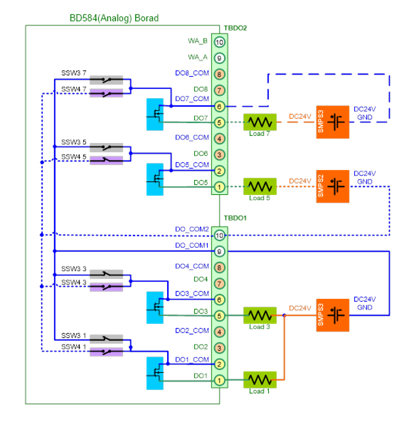
Figure 5.62 Method for Connecting the Digital Output on Analog Board (BD584)
The installation order can be summarized as follows.
① First, turn off both SIP switches (SSW3 and SSW4).
② Connect the load and external power to the output terminal blocks TBDO1 and TBDO2.
③ SIP switch SSW3 and SSW4 setting: For the power configuration, turn the SIP switches SSW3 and SSW4 ON or OFF according to the applicable load.
| Caution: You must not set the same switch number for SIP switches SSW3 and SSW4 to ON simultaneously. Doing so can short-circuit two different power supplies. |

Similarly to the input, the SIP switches SSW3 and SSW4 are connected inside the board, as shown in Figure 5.59 below.
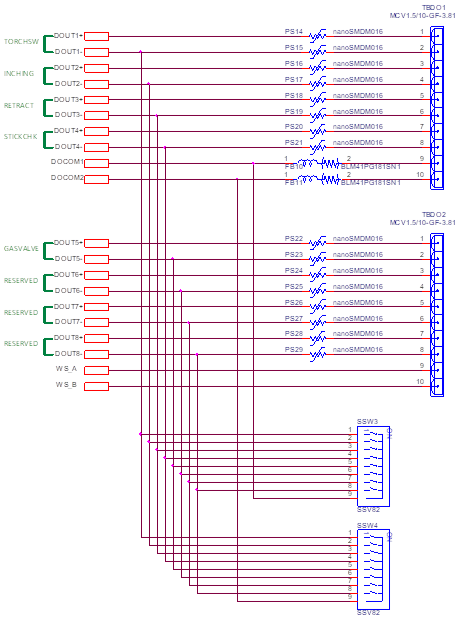
Figure 5.63 Common Circuit of Digital Output on Analog Board (BD584)
| Caution: You must not set the same switch number for SIP switches SSW3 and SSW4 to ON simultaneously. Doing so can short-circuit two different power supplies. |