5.9.2.1. Digital Input
5.9.2.1. Digital Input
The board has 8 digital input ports that can receive ON/OFF input. The photocoupler is used to electrically insulate from the external device. To expand the applied scope, each input can select and use the common input signal of two types.
The current used in the unit input is 5mA at 24V voltage. Therefore, if all 8 inputs are used, a total of 40mA of current is consumed.
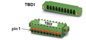
Figure 5.58 Terminal Block for Digital Input on Analog Board (BD584)
Use the assigned input to connect the arc welder. Details are shown in Table 5-25 below.
Table 5‑33 Pin Configuration of Digital Input Terminal Block (TBDI) of Analog Board (BD584)
Number | Name | Name for Arc Welder Connection | Remarks |
1 | DIN1 | WCR |
|
2 | DIN2 | SHOCK_SENSOR |
|
3 | DIN3 | WIRE_STICK |
|
4 | DIN4 | WELDER_ERR |
|
5 | DIN5 | WIRE_STATE |
|
6 | DIN6 | GAS_STATE |
|
7 | DIN7 | Reserved 1 |
|
8 | DIN8 | Reserved 2 |
|
9 | DI_COM1 | Signal Common 1 |
|
10 | DI_COM2 | Signal Common 2 |
|
The method of connecting the digital input port is shown in Figure 5.55 below. The example depicts the connection of 4 sensors with contact point or NPN-type output. Sensors 6 and 8 are configured with SMPS1 power, and Sensors 1 and 4 are configured with SMPS2 power. That is, two different types of power input can be used. This is set and classified by the SIP switches, SSW1 and SSW2 inside the board. For example, sensor 8 is connected to input port 8. Because this sensor uses SMPS1 power, the circuit must be configured through the COMMON power connected to 9. Therefore, turn on SSW1 switch 8, and then turn off SSW2 switch.
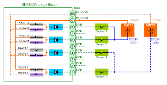
Figure 5.59 Method for Connecting Digital Input on Analog Board (BD584)
The installation order can be summarized as follows.
① First, turn off both SIP switches (SSW1 and SSW2).
② Connect the sensor and external power to the input terminal block TBDI.
③ SIP switch (SSW1 and SSW2) setting: For the power configuration, turn the SIP switches SSW1 and SSW2 ON or OFF according to the applicable sensor.
| Caution: You must not set the same switch number for SIP switches SSW3 and SSW4 to ON simultaneously. Doing so can short-circuit two different power supplies. |

SIP switches SSW1 and SSW2 are connected within the board, as shown in Figure 5.56 below. Because the DI_COM1 (#9 pin) of digital input terminal block TBDI is connected to the common connecting pin (#9 pin) of SIP switch SS1, when you turn ON switches #1~#8 of SSW1, the same power as DI_COM1 is connected to the input signal processing circuit.
In addition, because the DI_COM2 (#10 pin) of TBDI is connected to the common connecting pin (#9) of SIP switch SSW2, when you turn ON switches #1~#8 of SSW2, the same power as DI_COM2 is connected to the input signal processing circuit.
Switches #1~#8 of SSW1 and SSW2 are connected to each other for each number. Therefore, if you turn ON both SSW1 and SSW2 for the input signal number, the common power will be short-circuited. For this reason, you must only turn ON one of the two.
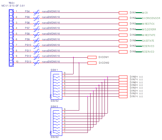
Figure 5.60 Common Circuit of Digital Input from Analog Board (BD584)
| Caution: You must not set the same switch number for SIP switches SSW3 and SSW4 to ON simultaneously. Doing so can short-circuit two different power supplies. |