7.6.1. Optimize axis origin and tool length
7.6.1. Optimize axis origin and tool length
This is to calibrate the zero point of each axis of the robot as well as the tool length, without using an external measuring sensor.
When it comes to the teaching method, you need to prepare two pointed tips, and then fix one tip externally and the other one at the tool. After that, you need to carry out the recording for multiple points by using the robot program only by changing the posture of the tool end of the robot against the externally fixed tip.
At this time, 7 points should be taught when both the axis origin and the tool length are to be found, while 4 points or more should be taught when only the tool length is to be found
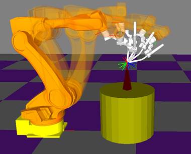
Figure 7.92 Teaching method for optimizing the axis origin and the tool length
When this function is used, not only the tool lengths, X, Y and Z, which have no CAD data, but also the zero points of the H, V, R2, and B axes of the robot can be located by using the optimization method.

l When this function is used, the encoder offset and the tool length will be changed, leading to a change in the work position of the previously taught program. Thus, the user must use this function before performing work.
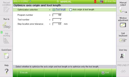
Figure 7.93 Results of the axis origin and tool length optimization
n Setting
① Tool length
The set value is adjusted from the tool length set in 『[F2]: System』 → 『3: Robot parameter』 → 『1: Tool data』
② Axis origin & tool length
- This function needs to be selected to calibrate both the zero point and the tool length of the robot. Generally, this is used to set the correct zero point initially after installing the robot.
- The tool length that should be set from 『[F2]: System』 → 『3: Robot parameter』 → 『1: Tool data』 and the robot’s zero point that should be set from 『[F2]: System』 → 『3: Robot parameter』 → 『2: Axis origin』will be automatically calculated.
- When you need to execute 『[F2]: system』 → 『3: Robot parameter』 → 『1: tool data』 → 『angle calibration』, it is necessary to implement 『angle calibration』 after completing the 『Optimize axis origin and tool length』. Also, precise data tool should be set.
- Once after the robot’s zero point is set correctly, you need to shift the optimization selection method to the ‘tool length’ option in order to calibrate the tool length only. When the ‘axis origin and tool length’ is changed, the zero points of all of the robots will change. So pay attention as the location of the previously prepared program will change.
n Program number
This sets the program number that records the same point in various positions.
n Tool number
This is the tool number to automatically set and it must be same with the tool number recorded in the program for setting.
n Allowed position error
If the expected error following the auto calibration setting is smaller than the value set here, the constant data will be updated automatically. If the expected error is bigger than value set here (Initial set value 0.1mm), it will be checked with the user first whether to reflect the constant, before making it reflected.

l In this function, the correctness of the teaching is proportionate to the correctness of the maximum step position error result. Accordingly, it is required to prepare, if possible, two pointed tips and carry out the teaching in a way that correct matching can be made possible. Make sure that the correctness in matching between the tool end and the fixed point in space is within 0.5mm when visually checked.
l Teach so that the posture of each step should not be similar to each other, and the new posture should be different (Different by 30dge or higher) from the previous one.
l Teach so that the movement of the wrists (R2, B, and R1) of each step is large as possible and so that the angle difference of each step is enough (as wide as possible).
l When the machine parameter file (ROBOT.MCH) is set as being protected, this function cannot be run. Try after canceling the file protection