4.1.7. Tool
4.1.7. Tool
Tool could be configured up to 16 and it is modeled by several spheres. Each tool model consists of up to 6 spheres. Tool model is used for monitoring cell area and cartesian spaces. TCP is monitored by TCP speed limits. Only one tool could be activated through safety I/O signal.
TCP position should be configured based on robot flange coordinate system(Xf, Yf, Zf in Figure 3-7). Each tool’s TCP position should be same with robot controller’s tool data because robot monitoring function checks that SafeSpace’s tool number and TCP position are same with robot controller’s.
The spheres for tool modeling consist of center and radius. The sphere’s center should be set based on robot flange coordinate system. These parameters are independent of the tool data set in robot controller. The radius must be large enough to cover the current tool size and stopping distance at maximum TCP speed.
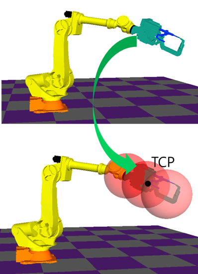
Figure 4.6 Tool modeling
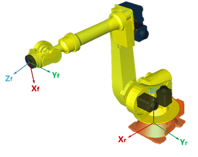
Figure 4.7 Robot flange coordinate system
Table 4‑7 Tool parameters
Tool parameter: Tool 1~16 | |||
Parameter name | Value | Description | |
Name | Name string | Max. 24charaters. Default=“Joint Space n“ ※ Used in the the HRSafeSpace only. Name is not transferred to the SafeSpace from the robot controller. | |
TCP | X | -10,000~ 10,000(mm) | XYZ coordinate values of TCP Default: 0 |
Y | |||
Z | |||
Properties: Sphere1~6 | |||
On/Off | On/Off | Off=This sphere is not monitored On=This sphere is monitored Default: On(Sphere1), Off(Sphere2~6) | |
Center | X | XYZ coordinate values of a sphere’s center in flange coordinate system. Default: 0 | XYZ coordinate values of a sphere’s center in flange coordinate system. Default: 0 |
Y | |||
Z | |||
Radius | 0~10,000 (mm) | Radius of a sphere Default: 1,000(mm) | |