7.1.1. Monitoring in detail
7.1.1. Monitoring in detail
This function is used for checking data related to arc welding. As the information may vary depending on the type of the set welders, the relevant monitoring window may also vary depending on the type of the set welders. When there is an error in the communication with the welders or the communication channel is not connected, the “Welder error code” or “Welder communication state” section will be displayed in red. For the GB2/GZ4/GE2 welders, the following data can be checked via the detailed data monitoring function.
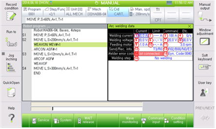
Figure 7.1 Arc welding Monitoring in detail
(1) Actual welding current outputted in the welder (A).
(2) Welding current limit. Indicate as ‘---’ in case arc limit monitoring function is not used.
(3) Command welding current outputted from the robot to the welder (A).
(4) Arc short circuiting frequency for 1 sec.
(5) Actual welding voltage (V) generated from current welder.
(6) Welding voltage limit. Indicate as '--.-' when not using the arc limit monitor function.
(7) Reference welding voltage offset value (V) generated from the robot to the welder.
(8) Offset value + synergic voltage. In other words, target output voltage (V).
(9) Current value (A) that drives the actual feeding motor.
(10) Indicated as “--.-” when the feeding motor arc limit monitoring function is not used.(A)
(11) Feeding motor rotation speed (rpm).
(12) T: command send frequency, R: command receive frequency.
(13) R: retry frequency, B: busy detection frequency, N: NG frequency, E: error frequency.
(14) Welder error code.
(15) Synergic code delivered via welder.
(16) Welding procedure