7.5. Sensor-based arc welding data monitoring function
7.5. Sensor-based arc welding data monitoring function
This function enables different monitoring functions by sending data from power and voltage sensors to controllers. In general, a welding machine that is connected through digital communication sends welding current and voltage to controllers, whereas the one that is connected through analog communication doesn't send the welding data. For some digital welding machines, the sent data are way distorted (different from the original one) and its sending cycle is slow, making it unsuitable for functions. This is the sensor-based arc welding data monitoring function to measure limited welding machine data with sensor to use it.
The following is the list of current arc welding robot monitoring functions:
(1) Real-time monitoring (detailed information, waveform, and large screen)
(2) Arc welding data storage function
(3) Arc welding data management function
(4) Arc welding result quantification function
(5) HRMS arc welding data monitoring function
If a welding machine doesn't provide the robot controller with welding data, all of the functions will not be available. In addition, if data are distorted, incorrect data will be used for management, so the sensor-based arc welding data monitoring will be useful for the following:
(1) A welding machine that doesn't provide robot controllers with welding data
(2) A welding machine that has serious welding data distortion
(3) A welding machine that has very slow sending cycle

If this function is used, only data from the sensor are used instead of those from the welding machine.
To use this function, connecting the sensors to measure current and voltage during welding is required, and communication device to send measured welding data to controllers. Both digital and analog communication types are available and either of them can be selected according to field conditions. Here is the system structure by communication type.

Figure 7.10 Structure drawing of sensor-based arc welding data monitoring (digital communication)

Figure 7.11 Structure drawing of sensor-based arc welding data monitoring (analog communication)
Go to 『[F2: System]』 → 『4: Application Parameter』 → 『2: Arc Welding』 → 『[F2: Sensor-based Monitoring]』 to set this function.
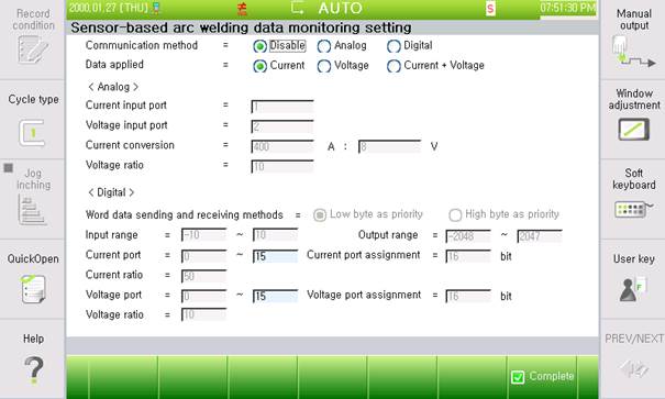
Figure 7.12 Sensor-based arc welding data monitoring (settings screen)
(1) Communication type: Communication-type setting to receive data from current and voltage sensors
(2) Data to apply: Data to apply this function. (Sensor data are used instead of welding machine data for this function.)
(3) <Analog>
A. Current input port: The output of the current sensor is connected.
B. Voltage input port: The output of the voltage sensor is connected.
C. Current conversion: The ratio between a value from the sensor and the actual current, frequently found in sensor specifications
D. Voltage multiplying factor: The ratio between a value from the sensor and the actual voltage
(4) <Digital>
A. Word data communication type: There is a difference between sending lower and upper bytes when communicating Word data according to communication. DeviceNet uses the lower byte preferred type in general.
B. Input range: In communication module specifications, set the range of the input values from sensors to communication modules.
C. Output range: In communication module specifications, set the range of the input values to convert and output.
D. Current port: Port to receive the output of the current sensor
E. Current port assignment: Number of ports to receive
F. Current multiplying factor ratio between a value from the sensor and the actual current
G. Voltage port: Port to receive the output of the voltage sensor
H. Voltage port assignment: Number of ports to receive
I. Voltage multiplying factor: Ratio between a value from the sensor and the actual voltage
Our high-voltage touch sensing unit includes current and voltage sensors, so this function can be connected just by adding a communication module. Welding current and voltage will be available by connecting output values with the communication module and enabling the sensor-based arc welding data monitoring function.
The following are examples of connection and settings when using the high-voltage touch sensing unit. (It depends on the specifications of high-voltage touch sensing unit and communication module.)
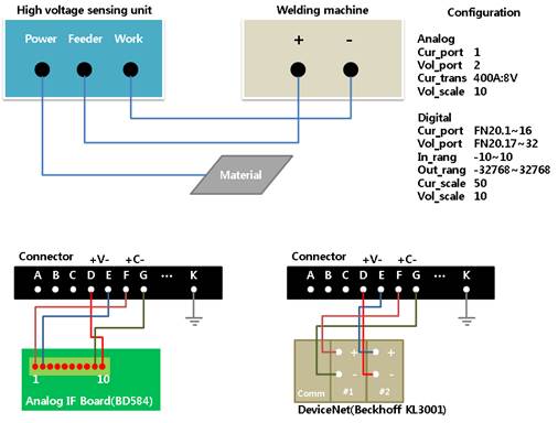
Figure7.13 High-voltage touch sensing unit and sensor-based arc welding data monitoring