4.3.5.6. BD558T (Hi5a-T Controller Integrated Drive Unit)
4.3.5.6. BD558T (Hi5a-T Controller Integrated Drive Unit)
The drive unit performs the power amplification function that allows the current to flow to each phase of the motor according to the current command from the servo board. The six-axis integrated drive unit can drive six motors at the same time and is configured, as shown below.
The diode module converter is integrated with the servo amp, rectifies and coverts the three-phase current supplied from the electric module into direct current using the diode module, and stores it into a smoothing capacitor. Then, the power generated from the motor when the robot decreases in speed is to be consumed through transistors and resistors. The converter is configured as follows.
Table 4-66Configuration of the BD558T (Hi5a-T 6-Axis Integrated Drive Unit)
Components | Functions | |
| Logic unit | Separates the PWM signal from the servo board into the IPM upper/lower driving signals and performs error processing |
Gate drive module | Generates the IPM gate signal | |
Gate power module | Generates the gate power | |
Current detection unit | Detects the current that flows through the motor | |
Rectifier | Generates the DC power from AC power that will be supplied to the motor | |
Regenerative control | Drives IGBT when the PN voltage increases | |
Error detection unit | Detects overvoltage, regenerative resistor overheating, and surge input errors | |
Control power unit | Generates the control power (: 5 V, ± 15 V) | |
Pre-charge unit | A power sequence unit that protects the DC power smoothing capacitor | |
| Heat sink | Dissipates the heat generated from the power devices |
IPM | Switching device | |
Capacitor | Smoothens the DC power | |
Regenerative IGBT | Performs regenerative control | |
Regenerative resistor | Consumes regenerative power | |
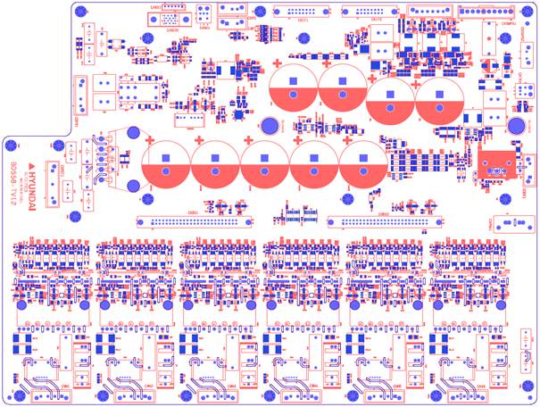
Figure 4.62 Parts Allocation Diagram of the BD558T
Table 4-67Description of the Connectors for BD558T
Name | Usage | Connection of External Units |
CNRST1 | 220 V Three-Phase (: R, S, T) Power Input | Magnetic Connector |
CNPR1 | 220 V Single-Phase (: R, T) Power Input | Magnetic Connector |
CNM1–6 | Power PWM Output | Three Phases of Each Axis Motor |
CNBS1–2 | PWM Signal, Error Signal, Gate Power Supply | Servo Board (BD544) Interface |
CNPNA1 | Additional Axis Power Supply | Additional Axis AMP |
CNDR1 | Regenerative Resistor Connection | Regenerative Resistor |
CNSMPS1 | External SMPS Power Input | External SMPS |
CNSMPS2 | Sequence Board Power Supply | Sequence Board (BD567T) |
CNP1 | External Power Supply (24 V) | - |
CNP2 | External Power Supply (5 V) | - |
CNPOW1 | Control Power Supply (5 V, ±15 V) | Back Plane Board |
CANIO1 | CAN Communication 2PORT, Operation Sequence Signal | Mainboard (BD511) |
CANS1 | CAN Communication 1PORT | - |
CANU1 | External CAN Communication 1PORT | - |
CNIF1 | Operation Sequence Signal | Sequence Board (BD567T) |
CNIF2 | Operation Sequence Communication Signal | Sequence Board (BD567T) |
Table 4-68 Type Symbol of the Hi5a-T 6-Axis Integrated Drive Unit
Classification | Type Symbol |
Servo Drive | BD558T/BD558T-S |
Table 4-69 Specification of the Hi5a-T 6-Axis Drive Unit
Item | Classification | Applicable | ||
IPM Capacity | 3A | 3B | HH4, HH4L, HH7, HH8 | 6-Axis Integrated |
Year | 00–99 | Production Year: 2000–2099 | ||
Month | 01–12 | Production Month: January–December | ||
Serial No. | 001–999 | Monthly Production Quantity: 1–999 Units | ||
Table 4-70 Capacity of the Hi5a-T IPM
Small | A | (IPM Current Rating) 50 A, (Hall Sensor Current Rating) 4 V / 15 A |
B | (IPM Current Rating) 20 A, (Hall Sensor Current Rating) 4 V / 5 A |
Table 4-71 Hall Sensor Symbol for Hi5a-T IPMs
Drive Model | Hall Sensor Symbol (Specification) | Full-Scale Current (Im) | IPM Specification (Rated Current) |
Small Servo Drive | 3 (4 V / 15 A) | 28.12 Apeak | PSS50S71F6 (50 A) PSS20S71F6 (20 A) |
5 (4 V / 5 A) | 9.37 Apeak |
Table 4-72 Specification of Hi5a-T 6-Axis Integrated Regenerative IGBT
Regenerative IGBT | z | 60 A Regenerative Resistor, 20 Ω 150 W 1 EA can be applied |
Table 4-73 Specification of Hi5a-T 6-Axis Integrated Electrolytic Capacitor
Electrolytic Capacitor | 5c | 470 uF 5 EA |
* For IPM, hall sensors, IGBT, and electrolytic capacitors, the dedicated parts for the Hi5a-T controller should be used.
| Caution: Because the drive unit differs depending on the robot, you must check the model when replacing it. |
