4.3.5.1. SD3X3Y (Medium-Size) and SD3L3Y (Large-Size) 6-Axisintegrated Drive Unit
4.3.5.1. SD3X3Y (Medium-Size) and SD3L3Y (Large-Size) 6-Axisintegrated Drive Unit
The drive unit plays a role of amplifying power by sending current to each motor according to the current command from the servo board. The 6 axis all-in-one drive unit can operate 6 motors at the same time, and the following table shows its components.
Diode module converter is integrated with servo amp, and the 3-phase current from the electric module is rectified with a diode module; converted to DC; and stored in the smoothing capacitor. When the speed of the robot is reduced, power generated from a motor is consumed through a transistor and resistance. The diode module converter is constructed as shown below.
Table 4‑36 The Components of SD3X3Y (Medium-Size) and SD3L3Y (Large-Size) 6-Axis integrated Drive Unit)
Component | Function | |
BD552 (Logic Board) | Separation of the PWM signal from the servo board into upper and lower IPM drive signals, and execution of error processing | |
BD551 (IPM Board) | Gate Drive Module | Generation of IPM gate signals |
Gate Power Module | Generation of gate power | |
Current Detection Unit | Detection of the current flowing into the motor | |
BD561 (Converter Board) | Rectifier Unit | Generation of DC power circuit provided from the AC input main power. |
Regenerative Control | Drive of IGBT if PN voltage increases | |
Error Detection Unit | The detection of overvoltage, overheated regenerative resistance, and bibliographic data input errors | |
Other Components | Heat Sink | Emits heat generated by power modules |
IPM | Switching Device | |
Capacitor | DC power smoothing | |
Regenerative IGBT | Execution of regenerative control | |
n Type number system of medium(Lagre) 6-axis integrated drive unit
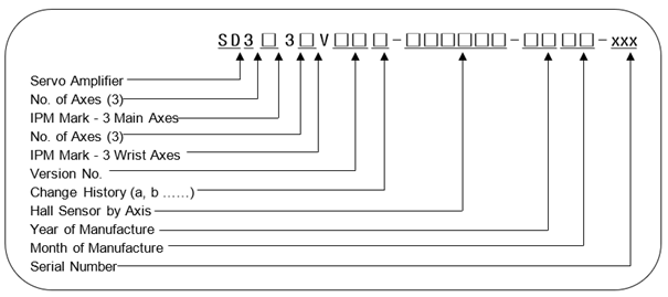
Table 4‑37 Type code of medium(Large) 6-axis integrated drive unit
Classification | Mark of Type |
Servo Drive | SD |
Table 4‑38 Specifications of medium(Large) 6-axis integrated drive unit
Item | Classification | Application | ||
IPM Capa. | 3X | 3Y | HS180, HH300, HX400 | 6-Axis integrated Type |
4X | 2Y | HC2502B2D, HC2503B2D | ||
3L | 3Y | HC3303B1DA, HC3303B2DA | ||
Year | 00 ~ 99 | Year of Manufacture: 2000 ~ 2099 | ||
Month | 01 ~ 12 | Month of Manufacture: 1 ~ 12 | ||
Serial No. | 001 ~ 999 | No. of units manufactured per month: 1 ~ 999 | ||
Table 4‑39 Medium(Large) Size IPM Capacity
Medium Size(Large Size) | L | (IPM Rated Current) 150A, (Hall Sensor Rated Current) 4V/75A |
X | (IPM Rated Current) 100A, (Hall Sensor Rated Current) 4V/50A | |
Y | (IPM Rated Current) 75A, (Hall Sensor Rated Current) 4V/50A | |
Z | (IPM Rated Current) 50A, (Hall Sensor Rated Current) 4V/25A |
Table 4‑40 Hall sensor code for medium(Large) IPM
AMP Model | Hall Sensor Mark (Spec.) | Full-Scale Current (Im) | AMP Feedback Constant (Iv) |
Medium (Large) servo drive unit | 0 (4V/75A) | 140.62Apeak | PM150CL1B060(150A) |
1 (4V/50A) | 93.75Apeak | PM100CL1B060(100A) PM75CL1B060(75A) PM50CL1B060(50A) | |
2 (4V/25A) | 46.87Apeak | ||
3 (4V/15A) | 28.12Apeak | ||
4 (4V/10A) | 18.75Apeak | ||
5 (4V/ 5A) | 9.37Apeak |
Table 4‑41Specifications of medium(large) 6-axis regenerative IGBT
Regenerative IGBT | L | 150A, Regenerative Resistance: 2Ω 2000W 2EA Applicable |
Table 4‑42 Specifications of medium(large) 6-axis integrated electrolytic condenser
Chemical Condenser | 2C | 3300uF 2EA |
| Caution: As the drive unit varies depending on the robot, so please check out the form of it in replacing it. |

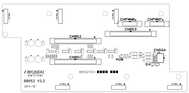
Figure 4.55 BD552 Component Layout
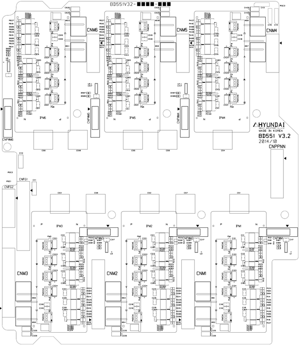
Figure 4.56 BD551 Component Layout
Table 4‑43 BD552 Connector
Name | Use | External Device Connection |
CNBS1, 2, 3 | PWM Signal and Error Signal | Servo Board(BD544) CNBS1,2,3 |
CNSGA | /PWMON, SVERR, BRAKE | Sequence Board (BD530) CNSGA |
CNPWM 1~6 | PWM Signal and Error Signal | Servo Amp BD551 CNPWM1~6 |
CNPWM 7~8 | Additional Axis PWM Signal and Error Signal | Option Board(BD554) CNPWM |
Table 4‑44 BD551 Connector
Name | Use | External Device Connection |
CNM 1~6 | Motor Connection | CMC1, CMC2 |
CNPWM 1~6 | PWM signal and error signal | Servo Amp BD552 CNPWM1~6 |
CNPPNN | Power for motor drive | Drive Power Unit (BD561) CNPN1 |
CNFG1 | The frame ground of the Main axis motor | CMC1 |
CNFG2 | The frame ground of the Wrist Axis motor | CMC2 |
Table 4‑45 BD552 LEDs
Name | Color | Status Display |
SV | Yellow | ON if PWM is ON |
POW | Green | OFF if current dip/sag occurs |
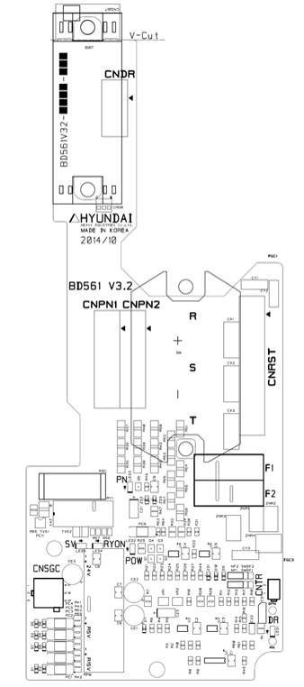
Figure 4.57 BD561 Component Layout
Table 4‑46 Description of BD561 connector
Name | Use | External Device Connection |
CNRST | 3-Phase Power Input | Electrical Module CNRST |
CNSGC | /PWMON, OV, FLT, FB | Sequence Board(BD530) CNSGC |
CNDR | Regenerative Power Output | Regenerative Resistance |
CNTR | Detection of Overheated Regenerative Resistance | Thermal Sensor of Regenerative Resistance |
CNPN1 | For Supply of PN Power | 6-Axis Servo Amp CNPPNN, Additional Axis CNPN |
CNPN2 | For Supply of PN Power | Additional Axis Servo Amp |
Table 4‑47 Description of BD561 LED
Name | Color | Status Display |
SV | Yellow | ON if PWN is ON |
POW | Green | OFF if control voltage sag occurs |
DR | Red | ON if regenerative power discharge operates |
PN | Red | ON if PN voltage is over 42V |
RYON | Red | OFF if PN power discharge operates |