4.2. The Arrangement of Parts
4.2. The Arrangement of Parts
Table 4-1 shows the main parts of Hi5a-S00/S10/J00 controller and the name of each part, and Figure 4.8, 4.9, and 4.10 shows the arrangement of them.
Table 4‑1 The Name of Each Part of Hi5a-S00/S10/J00 Controller
No. | Type | Item |
1 | RACK | Rack |
2 | BD502 | Backplane Board |
3 | SR1 | DC Multi Power Unit(SMPS: HDI-191) |
4 | BD511 | Main Board |
5 | BD544 | Servo Board |
6 | BD530/531 | System Board |
7 | PSM30 | Middle-Size Electrical Module |
7-1 | PSM15 | Small-Size Electrical Module (Hi5a-S20/S30) |
7-2 | PSM50 | Large-Size Electrical Module (Hi5a-S80) |
8 | SD3X3Y | Middle-Size 6-Axis Servo Drive Unit (Standard Specifications) |
8-1 | SD3A3D | Small-Size 6-Axis Servo Drive Unit (Hi5a-S20/S30) |
9 | SD1X | 100A 1-Axis Drive Unit (Option) |
9-1 | SD1Z | 50A 1-Axis Drive Unit (Option) |
9-2 | SD1L | 150A 1-Axis Drive Unit (Option) |
10 | EM. SW. | Emergency stop switch |
11 | CNRJ45 | User Ethernet Port |
12 | NFB | No Fuse Breaker |
13 | FAN1 | Rack cooling fan |
14 | FAN2 | Drive unit cooling fan |
15~17 | FAN3~5 | Servo drive unit cooling fan |
18 | NFT1 | Noise Filter |
19 | RDR1 | Regeneration discharge resistance (Standard Specifications) |
20 | RDR1 | Regeneration discharge resistance (Hi5a-S30) |
21 | TR2(optional specifications) | Input power transformer |
22 | CMC1 | Power Cable Lead-In Connector for Motor Drive 1 |
23 | CMC2 | Power Cable Lead-In Connector for Motor Drive 2 |
24 | CEC1 | Motor Encoder Communications Cable Lead-In Connector |
25 | CNRTP | Teach pendant Cable Lead-In Connector |
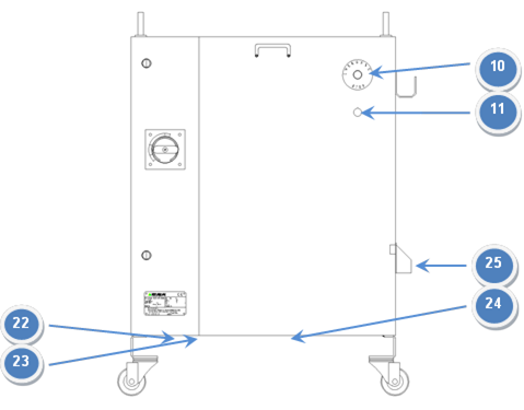
Figure 4.8 Hi5a-S00 Part arrangement parts in the exterior of a controller
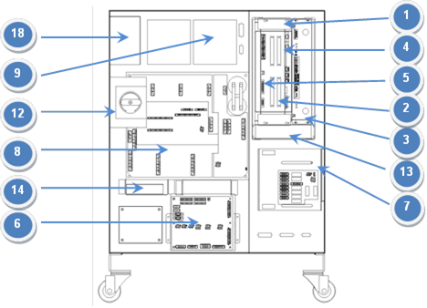
Figure 4.9 Part arrangement in the interior of the front surface of the Hi5a-S00 controller
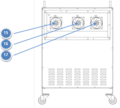
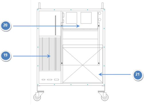
Figure 4.10 Hi5a-S00 Part layout on the back side of controller
Table 4-2 shows the main parts of Hi5a-C3*/C4*/C5*/C6* controller and the name of each part, and Figure 4.11, 4.12, 4.13 and 4.14 shows the arrangement of them.
Table 4‑2 The Name of Each Part of Hi5a-C3*/C4*/C5*/C6* Controller
No. | Type | Item |
1 | RACK | Rack |
2 | BD502 | Backplane Board |
3 | SR1 | DC Multi Power Unit (SMPS: HDI-191) |
4 | BD511 | Main Board |
5 | BD544 | Servo Board |
6 | BD530/531 | System Board |
7 | PDM30 | Electrical Module |
8 | SR4 | DC power supply for falling prevention brake of elevation axis |
9 | SD3X3Y | Middle-Size 6-Axis Servo Drive Unit (Standard Specifications) |
9-1 | SD1L5X | HC2500B2D-*-1* (Option) |
9-2 | SD4X2Y | HC2501B2D-*-1* (Option) |
9-3 | SD3X3Z | HC2501B1D-*-1* (Option) Middle-Size 6-Axis Servo Drive Unit (Hi5a-C35) |
9-4 | SD3L1Y | HC3303B1D / HC3303B2D Large-Size 4-Axis Servo Drive Unit (Hi5a-C5* 사양) |
9-5 | SD3L3Y | HC3303B1DA / HC3303B2DA Large-Size 6-Axis Servo Drive Unit (Hi5a-C5* 사양) |
10 | BD58A | LDIO board |
11 | BD58B | Safety relay board |
12 | CNRJ45 | User Ethernet Port |
13 | EM. SW | Emergency stop switch |
14 | SR2 | DC power apparatus for a sensor |
15 | SR3 | DC power supply for robot fan |
16 | NFB1 | Breaker of driving device wiring (No Fuse Breaker) |
17 | NFB2 | Breaker for control power wiring (No Fuse Breaker) |
18 | TBMAIN1 | Terminal Block for inputting driving device power (Terminal Block) |
19 | TBMAIN2 | Terminal Block for inputting control power (Terminal Block) |
20 | TBPW1 | Terminal Block for interior power (Terminal Block) |
21 | FAN1 | Rack radiating fan |
22~24 | FAN2~4 | Servo-drive unit radiating fan |
25 | TR1 | Transformer |
26 | NFT1 | Line Noise Filter |
27~28 | DR1~2 | Regeneration discharge resistance |
29 | CMC1 | Power Cable Lead-In Connector for Motor Drive 1 |
30 | CMC2 | Power Cable Lead-In Connector for Motor Drive 2 |
31 | CEC1 | Motor Encoder Communications Cable Lead-In Connector |
32 | CNRTP | Teach pendant Cable Lead-In Connector |
33 | CIOC1 | Sensor cable inserted in the connector |
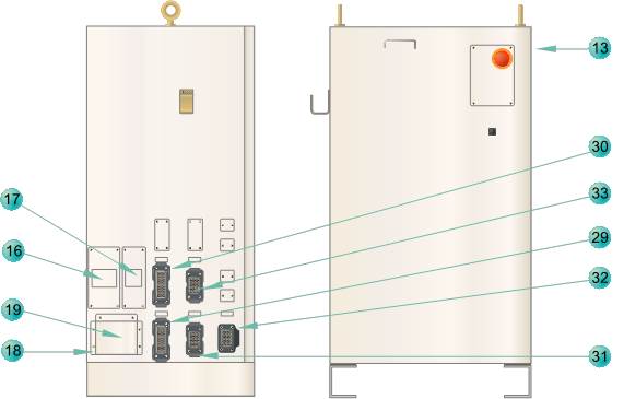
Figure 4.11Hi5a-C3*/C4* Part arrangement parts in the exterior of the controller
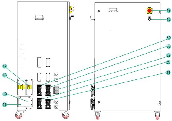
Figure 4.12 Hi5a-C5*/C6* Part arrangement parts in the exterior of the controller
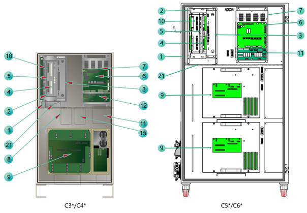
Figure 4.13 Part arrangement in the interior of the front surface of the Hi5a-C3*/C4*/C5*/C6* controller
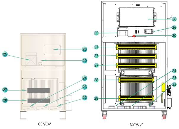
Figure 4.14 Part arrangement in the interior of the rear surface of the Hi5a-C3*/4*/C5*/C6* controller
Table 4-3 shows the main parts of Hi5a-P10/P20 controller and the name of each part, and Figure 4.15 and 4.16 shows the arrangement of them.
Table 4‑3 The Name of Each Part of Hi5a-P10/P20 Controller
No. | Type | Item |
1 | PRESSURE GAUGE | PRESSURE GAUGE |
2 | DOOR LAMP | DOOR LAMP |
3 | EM. SW | EMERGENCY SWITCH |
4 | NFT1 | NOISE FILTER |
5 | NFB1 | Breaker of driving device wiring (No Fuse Breaker) |
6 | SD1X | 100A 1-Axis Drive Unit (Option) |
6-1 | SD1Z | 50A 1-Axis Drive Unit (Option) |
6-2 | SD1L | 150A 1-Axis Drive Unit (Option) |
7 | RACK | Rack |
8 | BD544 | Servo Board |
9 | BD511 | Main Board |
10 | SR1 | DC Multi Power Unit (SMPS : HDI-191) |
11 | BD502 | Backplane Board |
12 | FAN1 | Rack cooling fan |
13 | PSM30 | Middle-Size Electrical Module |
14 | BD5C2 | electric board |
15 | SD3X3Y | Middle-Size 6-Axis Servo Drive Unit (Standard Specifications) |
16 | FAN2 | Drive unit cooling fan |
17 | BD5D1 | Encoder switch board |
18 | BD530/531 | System Board |
19 | BD5D0 | Air Purge control board |
20 | RDR1 | Regeneration discharge resistance (Standard Specifications) |
21 | AIR PURGE UNIT | AIR PURGE UNIT |
22 | TR2 (optional specifications) | Input power transformer |
23 | FAN3 | Servo drive unit cooling fan |
24 | FAN4 | Servo drive unit cooling fan |
25 | FAN5 | Servo drive unit cooling fan |

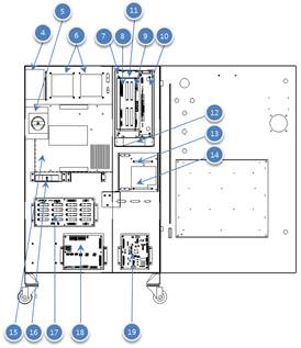
Figure 4.15 Part arrangement in the interior of the front surface of the Hi5a-P10/P20 controller
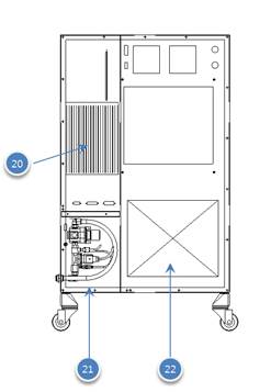

Figure 4.16 Hi5a-P10/P20 Part layout cover and on the back side of controller
The main components of the Hi5a-T10 controller and their names are as shown in Table 4-4 and are allocated as shown in Figures 4.17 and 4.18
Table 4‑4 Names of Individual Parts of Hi5a-T10 Controller
No. | Type | Part name |
1 | BD503T | Backplane board |
2 | BD525 | Communication board |
3 | BD544 | Servo board
|
4 | BD511 | Main board |
5 | LF1 | Noise filter 1 |
6 | TB1 | Terminal block 1 |
7 | RDR1 | Regeneration resistor 1 |
8 | BD558T | Power amplifier board |
9 | BD567T | System board |
10 | EARTH BAR1 | Earth bar 1 |
11 | MC1 | Magnet connector 1 |
12 | MC2 | Magnet connector 2 |
13 | SMPS1 | Control power supply system 1 |
14 | BD5B3T | External connector board |
15 | EARTH BAR1 | Earth bar 1 |
16 | MCCB1 | Breaker for the drive system wiring (not fuse breaker) |
17 | CNRTP | T/P contactor |
18 | MCCB1 | Breaker for the drive system wiring (not fuse breaker) |
19 | ACIN | External power input connector |
20 | CMEC1 | Internal power terminal block |
21 | UDIO | User digital input and output connector |
22 | SAFETY IO | Safety signal–related input and output connector |
23 | OPSIO | Operation-related input and output connector |
24 | CAN2 | External CAN communication connector 2 |
25 | RS-232 | External serial communication (RS232) connector |
26 | CAN1 | External CAN communication connector 1 |
27 | CNETN2 | External Ethernet connector 2 |
28 | CNETN1 | External Ethernet connector 1 |
29 | STOP | Stop switch and lamp |
30 | START | Operation switch and lamp |
31 | MON | Motor on switch and lamp |
32 | MODE | Operation mode switch |
33 | OPEM | Emergency switch |
34 | FAN1 | Servo drive system heat dissipation fan |
35 | FAN2 | Servo drive system heat dissipation fan |
36 | FAN3 | Servo drive system heat dissipation fan |
37 | FAN4 | Servo drive system heat dissipation fan |
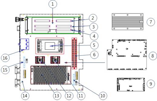
Figure 4.17 Hi5a-T10 Part arrangement parts in the interior of the controller
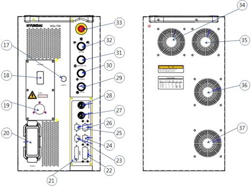
Figure 4.18 Part arrangement in the front and rear surfaces of the Hi5a-T10 controller