2.5.3.2. Base or Robot Recording Coordinate
2.5.3.2. Base or Robot Recording Coordinate
Location and position of the robot may be different depending on the coordinate. Generally if there is no driving axis, the Base coordinate and the Robot coordinate are the same. But when the driving axis is defined, the location and position of the robot tool will be different for the Base coordinate and Robot coordinate.
You can check by pressing the [Quick Open] key from the recorded MOVE command by selecting 『[F2]: System』 → 『1: User environment』 → 『1: Pose record type =<Base> or <Robot>』 in manual mode.

l To change the pose record format, consult the engineer.
l Because multiple positions exist for one tool end location/direction due to the mechanical characteristics, you must designate the robot type to define a unique position.
The robot type will be saved in [Pose parameter].CFG (P1.CFG, LP1.CFG) and each bit assignment of CFG is as the following.
bit 0 : (0: Designated, 1: Not designated)
Determines whether or not configuration pattern will be designated for posture that Robot currently poses. (If not designated, this will be automatically decided.)
bit 1 : (0: Front, 1: Rear)
If the tool end of the robot is in X axis + direction of the robot coordinate, select the front side, and if in – direction, rear side.
bit 2 : (0: Up, 1: Down)
This is the relationship between H axis and V axis.
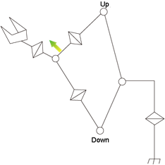
Figure 2.40 Up/Down posture
bit 3 : (0: Flip, 1: Non-flip)
Select Flip pattern if a coordinate is located at |R2|<90 against standard coordinate of the R2-axis, and select non-flip pattern if |R2|>=90.
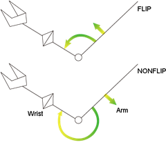
Figure 2.41 Flip/Non-flip posture
bit 4 : (0: |S|<180, 1: |S|>=180)
Select where angle of the S-axis is located at.
bit 5 : (0: |R2|<180, 1: |R2|>=180)
Select where angle of the R2-axis is located at.
bit 6 : (0: |R1|<180, 1:|R1|>=180)
Select where angle of the R1-axis is located at.
bit 7~9 : Represents coordinate system.
(0: Base, 1: Robot, 2: Angle, 3: Encoder, 4: User, 6: Master tool end)
bit 10~13 : User coordinate system number. (1~10)
l Designation of coordinate system is separated by additional character in the last for convenience of user as follow :
Base coordinate system = (X,Y,Z,Rx,Ry,Rz,cfg)
Robot coordinate system = (X,Y,Z,Rx,Ry,Rz,cfg)R
Axis coordinate system = (S,H,V,R2,B,R1)A
Encoder = (S,H,V,R2,B,R1)E
User coordinate system =(X,Y,Z,Rx,Ry,Rz,cfg)U è Number non-define method
User coordinate system =(X,Y,Z,Rx,Ry,Rz,cfg)Un è Number define method (1~10)