2.4. Monitoring
2.4. Monitoring
Helps the user monitor the state related to the servo tool change.
『[F1]: Service』 → 『1: Monitoring』 → 『19: Servo tool change』
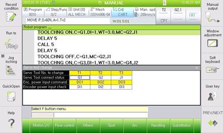
Figure 2.4 Servo Tool Change Monitoring
(1) Servo tool change function
Indicates whether the servo tool change function for the additional axis will be used
(2) Servo tool connection state
Indicates the connection/disconnection states of the servo tool for the additional axis. If it is connected, the item for the change will be displayed and if it is disconnected, “--”will be displayed.
(3) Encoder power supply output
Indicates the state of the output, together with the output signal for the encoder power supply
(4) Encoder power supply input
Indicates the state of the input, together with the input signal for the encoder power supply
Information)
l The logic of the input and output signals can be set by going through 『[F2]: System』 → 『2: Control Parameter』 → 『2: Input/Output signal setting』 → 『1: Input signal attribute』/『2: Output signal attribute』.
l The BD530 TBIO signals can be set in the number ranging 4097~4100.
l The TBIO signals of the robot program corresponds to DI [4097~4100]/ DO [4097~4100].