7.1. Function
7.1. Function
In order to perform weaving, weaving coordinates are needed for deciding the position for creating a weaving type trajectory as explained in 6.1. The set weaving coordinates can be used for setting the conditions of the weaving function in details.
Basically, when starting a weaving work, the z axis of the robot coordinates is set as the wall direction, and the access point and moving direction toward the welding start point will be used to allow the weaving coordinates (rectangular coordinates) to be created automatically.
However, in some cases, it would be impossible to generate weaving coordinates depending on some situations, such as positions of access points and types and positions of base metals, or it would be necessary to correct the set weaving coordinates (Ex. If the angle created between the wall direction and the other direction is not 90 degrees).
In such cases, the reference point function can be used to generate weaving coordinates as desired in a way that can match the weaving type with the base metal.
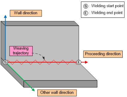
Figure 7.1 Weaving coordinate
(1) REFP 1 (Reference Point 1)
This command designates the wall direction. First, record a point on top of the basic material as REFP 1. Then, it will be possible to decide one single surface by using the welding path (Linear line ⓢⓔ) and the reference point 1. This surface can be set as the reference for the wall direction while carrying out weaving. If only the reference point 1 is set, other directions will set automatically by being rotated by 90 degrees based on the wall direction as the reference for the moving direction. This command is not used when setting the 'wall direction' based on the “Base on Torch”.
(2) REFP 2 (Reference Point 2)
This command determines the other direction by selecting the quadrant conducting the weaving. REFP 2 records a random point on top of the corresponding quadrant. In general, other directions are selected in the directions where there is an access point. [Figure 7-1] presents an example that shows weaving coordinates that are to be set when the reference point 2 is recorded in the space between the two base metals. If only the reference point 2 is set, other directions will be set by taking the z axis of the robot coordinates as the wall direction. The moving direction is the direction of moving from the weaving start point to the weaving end point. This command is not used when setting the 'wall direction' based on the “Base on Torch”.
(3) REFP 3 (Reference Point 3)
This command designates the proceeding direction of the weaving where the robot is stationary and only the positioner is rotating in stationary weaving.
(4) REFP 4 (Reference Point 4)
This is a command for setting the angle between the wall direction and the other directions. [Figure 7-1] shows an example in which the angle is set as 90 degrees. Designating the angle by using this command ignores any values set through [Basic pattern] →[Angle].
This command is not used when setting the 'wall direction' based on the “Base on Torch”.
(5) Standard for determining direction when without REFP
- Wall direction: Z-direction of the robot coordinate system
- Horizontal direction: Direction from wall towards the side of approach point
- Proceeding direction: Direction from weaving start point towards end point
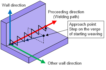

Figure 7.2 Weaving direction and reference point