6.4.7. Replacing Axis-B Reducer [HH007C]
6.4.7. Replacing Axis-B Reducer [HH007C]
(1) Set the controller to teaching mode and set the robot to standby [ON] condition. If the robot is not in standby [ON] condition, check whether the arm is sufficiently fixated to avoid it from dropping. And then proceed to (3).
(2) Turn the main power [OFF] with the controller power [OFF].
(3) By removing the bolts from the B-axis and R1-axis motor brackets, remove the timing belts.
(4) Remove the H/D housing, as shown in [Figure 6.13], and remove the wave generator.
(5) Remove the bearing support housing and the bearing housing as shown in [Figure 6.14].
(6) Remove the wrist body, and remove the bolts from the locking part of the B-axis reducer.
(7) Apply 9 g of grease (SK-1A) to the inside of the reducer in a thickness that matches the ball diameter of the wave generator..
(8) Mount a new B-axis reducer, and fasten the bolts at the locking part.
(9) Apply Threebond to the outer and inner wheels of the bearing as shown in the following figure, and insert the bearing into the axis of the wave generator..
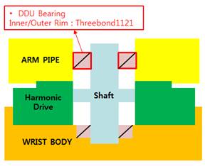
Figure 6.15 B-axis reduction gear Three Bond coating detail [HH007C]
(10) Connect the wave generator (replaced) to the axis, and insert it.
(11) Insert the wrist body into the arm pipe.
(12) By fastening the bolts of B-axis and R1-axis motor brackets, adjust the tension of the timing belts.
(B-axis belt: 3GT / Width: 6 mm / Belt’s unit mass: 2.5 / Span length: 193 mm / Tension: 29 N)
(R1-axis belt: 3GT / Width: 6 mm / Belt's unit mass: 2.5 / Span length: 119 mm / Tension: 29 N)
(13) Confirm that there is no error in robot's motion.
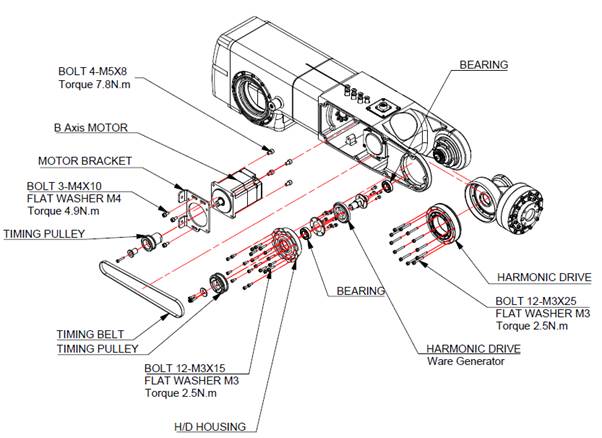
Figure 6.16 Axis-B Reducer Disassembly Diagram [HH007C]