2.3. DeviceNet setting
2.3. DeviceNet setting
DeviceNet is used to send and receive data between the robot controller and the laser controller. The basic communication cycle provided by Hi5a controller is 20msec. In order to improve the quality of laser welding, the speed of the relevant node has been enhanced to 10msec. The number of the node for which the speed can be enhanced will be read from the value inputted in 2.2 (6) DeviceNet node #. The user must input the node number first and then press the ‘Search node’ to update the scan list and then select ‘Apply’ and ‘Complete’. Users can refer to the manual related to the DeviceNet function for the contents for the setting.
『[F2]: System』 → 『2: Control parameter』 → 『2: Input and output signals setting』 → 『12: Built-in DeviceNet master information and setting』
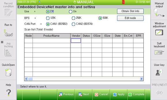
Figure 4 DeviceNet setting
(1) Whether to use
This should be set to ‘On’ for DeviceNet communication with the BlackBird laser controller
(2) Communication speed
500Kbps should be selected to secure the communication speed of 10msec.
(3) CAN port
CAN2 should be selected when using DeviceNet by adding the DB574 board.
(4) Scan list
When Search node is performed after the above settings are completed, the laser controller will be searched as a DeviceNet slave node. The node information includes the product name, sizes of sent and received data (bytes), communication speed (msec), etc. The node number can be set in the DeviceNet slave (the BlackBird laser controller), and the relevant node number will be scanned and shown in the robot controller.
(5) Definition of sent data
Type | Address | Name |
1 Byte | FNx.Y1 | Selection Program |
FNx.Y2 | Deselection Program | |
FNx.Y3 | Start Program | |
FNx.Y4 | Stop Program | |
FNx.Y5 | OTF-Trigger | |
FNx.Y6 | Ignore Scanner Temp | |
FNx.Y7 | Reset Interlock by extern | |
FNx.Y8 | Not Used | |
3 Byte | FNx.YB2 ~ FNx.YB4 | Not Used |
1 Byte | FNx.YB5 | Program number |
2 Byte | FNx.YB6 ~ FNx.YB7 | Robot Position X |
2 Byte | FNx.YB8 ~ FNx.YB9 | Not Used |
2 Byte | FNx.YB10 ~ FNx.YB11 | Robot Position Y |
2 Byte | FNx.YB12 ~ FNx.YB13 | Not Used |
2 Byte | FNx.YB14 ~ FNx.YB15 | Robot Position Z |
2 Byte | FNx.YB16 ~ FNx.YB17 | Not Used |
2 Byte | FNx.YB18 ~ FNx.YB19 | Robot Position RZ |
2 Byte | FNx.YB20 ~ FNx.YB21 | Robot Position RY |
2 Byte | FNx.YB22 ~ FNx.YB23 | Robot Position RX |
(6) Definition of sent data
Type | Address | Name |
1 Word | FNx.X1 | Interlock Closed |
FNx.X2 | Mode Auto | |
FNx.X3 | Request Scanner Position | |
FNx.X4 | Program Selected | |
FNx.X5 | Program Started | |
FNx.X6 | Program Finished | |
FNx.X7 | Program Stopped | |
FNx.X8 | Scanner Temp OK | |
FNx.X9 | Pilot Laser | |
FNx.X10 | OTF Sequence Ready | |
FNx.X11 | Step Finished | |
FNx.X12 | Program Mode OTF |