2.1. Tool parameter setting
2.1. Tool parameter setting
The setting of the additional axis to be performed basically for the execution of application is not necessary for laser welding. The laser scanner to be attached to the robot will be mounted to the end of the R1 axis by using a dedicated jig, and the tool coordinates should be inputted, as shown in the figure below, by taking into consideration the position (z-axis) where the laser enters the welding panel. Depending on the scanner mounting direction, the Y-axis rotation component may be included. The tool data depends on the specification of the scanner. The user may also use the 'Axis origin and tool length optimization' function to input the tool data more accurately. In this process, the end of the tool coordinate is used as an intersection point where the guide beam and the laser focus meet, and then a specific fixed point needs to be taught at more than four postures.
『[F2]: System』 → 『3: Robot parameter』 → 『1: Tool data』
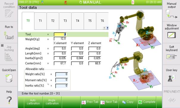
Figure 2 Additional axis parameter setting screen