2.2. Laser welding environment setting
2.2. Laser welding environment setting
Laser welding can be started by setting the 'BlackBird laser welding' screen. On this screen, it is required to set server information and trigger signal address to generate the recording file that will be provided to the BlackBird controller
『[F2]: System』 → 『4: Application parameter』 → 『27: BlackBird laser welding』
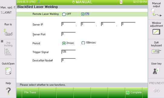
Figure 3 Laser welding setting
(1) Use of laser welding
The user must set the 'Use of laser welding' to the 'ON' mode before performing laser welding. In this state, the following inputs will be valid.
(2) Server IP
The server defined in this function refers to a PC that receives and stores the data defined as [Time - Robot position - Trigger signal] via UDP communication to generate the recording file required by the BlackBird controller. There are many methods to store the recording file, but the method in this setting is to store the data received as a recording file through UDP communication. In addition, a Windows-based PC that runs the BlackBird controller will be assumed as the server, which will be the easiest work.
(3) Server port #
This is for inputting the server port number for the socket communication together with the server IP. Currently, in the server program, the number is fixed to "20000" to make it unnecessary to input the port number.
(4) Sending cycle
The cycle of sending the data from the robot controller (client) to the server can be selected between 2msec and 100msec. Currently, 2msec is used for the recording file, while 100msec can be used for the monitoring. (Currently not used)
(5) Trigger signal (Welding section)
When the laser welding is performed, the laser controller determines the welding time by arbitrarily grouping welding points. If the signal is included in the DeviceNet data definition, it will be inputted as "FN6.5". (Input ".6.5") In addition, it is possible to increase the sending cycle by using separate hard wiring. In this case, it is required to input ‘123’ as a DO address for digital out.
(6) DeviceNet node#
The node number is to check the slave node number to improve the DeviceNet communication. In '2.3 DeviceNet setting', it is required to input the node number that is confirmed after node search is performed.
(7) Move file button
Pressing the relevant button after inserting the USB memory card, the user can move up to five recording files stored in the controller to the memory card. As the function is to move the files, they will not remain in the controller once moved.