1.2.1. Processes of Sensor Installation and LVS Welding Line Tracking
1.2.1. Processes of Sensor Installation and LVS Welding Line Tracking
A good understanding of the LVS function can minimize problems in the field. Mount the bracket on the torch to fix the sensor, as shown in the figure. In this process, performance may be degraded if the look ahead is too large. In general, α is 10–20 degrees.
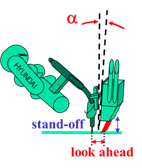
Figure 1.2 LVS sensor installation
If spatter is splashed on the LVS sensor, you can replace the covers that protect the laser receiving and emitting units. The LVS welding line tracking will be progressed by repeating the process of welding line sensing → target point calculation → cue related processing → position and posture error calculation → welding line tracking, as shown in the figure below.
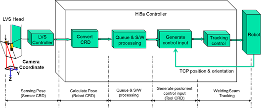
Figure 1.3 Principle of LVS tracking
Queue refers to a memory that stores these sequential target points. Regarding S/W processing, it refers to a variety of processing required for the LVS function, such as starting point search, end point search, spatter prevention, monitoring, stick-out correction, tracking amount limit, arc retry, arc restart, multipass, and seam finding.
The LVS function not only performs position traction but also makes it possible to set an option for automatically correcting the posture (orientation).
In this process, the Yaw, Pitch, and Yaw/Pitch options can be set.
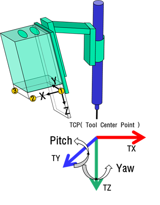
Figure 1.4 Principle of LVS tracking
* Safety precautions As the LVS function generates incremental commands, the robot may move on a path different from the previously taught path. That said, it is important for safety to set and use the traction amount limit function properly. Do not work close to the robot during teaching.