1.3. LVS Condition Settings
1.3. LVS Condition Settings
You can enter the condition edit window by pressing the QuickOpen key in the LVSON command.
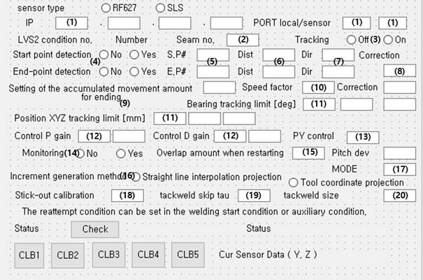
Figure 1.6 LVS condition edit window
(1) IP, PORT
As for IP, set the IP of the sensor or sensor controller.
Regarding the port, “local” is for the port of the controller, and “sensor” is for the port for the sensor.
(2) Seam number
This refers to a seam number registered in the LVS sensor. It gives a command for the LVS sensor to perform sensing with the seam number set in here.
(3) Tracking
It sets tracking as “enable” or “disable.” This tracking off function can be used conveniently when multipass welding is performed.
(4) Detection of the starting point and end point
It sets whether to search for the starting point or end point.
Starting point detection will occur, as shown in the figure below.
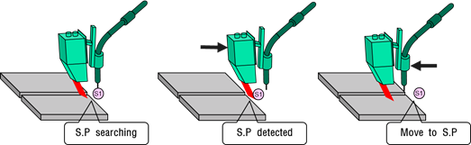
Figure 1.7 Example of enabled LVS starting point search
While starting point detection is enabled, if the LVSON command is executed, the search will start as shown in Figure 1.7.
When the starting point is searched, the robot will move to the starting point and store the information of the welding line that will be tracked afterward.
If starting point detection is disabled, tracking will start after movement occurs from the sensing starting point to the laser progressing direction, as shown in the figure below.
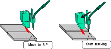
Figure 1.8 Example of disabled LVS starting point search
End point detection will occur, as shown in the figure below. If end point detection is used, it is possible to compensate for the end point error as much as , which is the TCP-laser strip distance.
In end point detection, welding will be performed by extending the end point to the point that the sensor does not determine to be a seam.
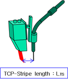
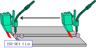
Figure 1.9 Example of LVS end point search
(5) Allocated pose number (S.P#, E.P#)
When the starting point search and end point search are completed, the pose will be recorded in the corresponding pose number.
(6) Search distance (Dist)
It sets the maximum search distance for the starting point search and end point search.
(7) Search direction (Dir)
If it is +1, searching will be performed in the direction of +ToolX, and if it is -1, searching will be performed in the direction of –ToolX.
(8) Correction (Search correction amount)
If there is a position error with the pose when the starting point search and end point search are performed, this function can be used to correct the error.
(9) Setting of the accumulated movement amount for ending
In Mode 4, tracking will end if movement occurred as much as the set distance (mm).
(10) Speed factor
It sets the movement speed to the end point when the end point search is enabled. In Mode 4, this refers to the movement speed in the forward direction.
(11) Position XYZ tracking limit and orientation tracking limit
It sets the error in comparison with the taught program. An error will occur when tracking is performed beyond this limit value.
(12) Control P gain and D gain
It sets a value within the range of 10–30. (In general, all values are used as 15.)
(13) PY control
If it is 0, only the position will be corrected, while orientation control will not be used. If the value is 1, 2, or 3, Pitch, Yaw, and Pitch & Yaw will be tracked along the welding line, respectively. When Mode 4 is to be used, 4 should be used for PY control.
(14) Monitoring
When the monitoring function is activated, tracking data can be collected in the 0001.GDT file.
(15) Overlap amount when restarting
It designates the overlap distance when restarting.
(16) Incremental generation method
It uses linear interpolation projection.
(17) MODE
This refers to the version of the LVS function. Mode 1 is for normal tracking, 3 for stationary tracking, and 4 for tracking without a MOVE statement.
(18) Stick-out correction
It can be used to adjust the wire stick-out length.
(19) Tack welding detection sensitivity
It sets the tack welding detection sensitivity. In general, values ranging from 0.7 to 0.1 are used.
(20) Tack welding length
It sets the tack welding length. For this distance, tracking will be ignored, and interpolation will proceed.
(21) The retry condition can be set in welding start condition – auxiliary condition.
(22) Crater treatment can be set in the crater backward distance item in the welding end condition.
(23) Pressing the [Check] button after the execution of the LVSON command will show the current status.