7.6.4.5. Menu composition
7.6.4.5. Menu composition
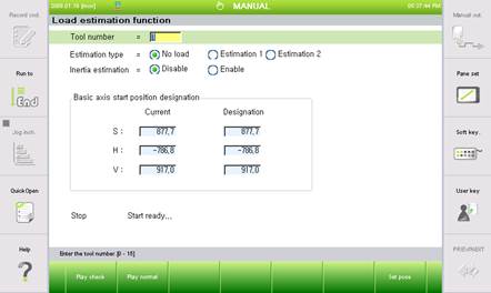
Figure 7.68 Load estimate setting
(1) Use the [SHIFT] + [←] [→] key to decide the tool number at the end of the current robot and the load estimate method number.
(2) Move the location of the robot so that the load calculation program does not interfere with the nearby jig and then press the 『[F7]: Set pose』key to designate the start position of the robot to execute the load calculation program.
(3) Press the 『[F1]: Play check』key to check whether the robot may collide with the surrounding objects. In case of collision risk, press the 『Emergency stop』key to stop the robot.
(4) After checking, press the 『[F2]: Play normal』key to start the load calculation.
(5) When <Load estimation 1> or < Load estimation 2> is selected, press the 『[F2]: Play normal』 key to run the pattern to obtain the load information. The robot controller will automatically calculate the load data and display the load data in the following screen.
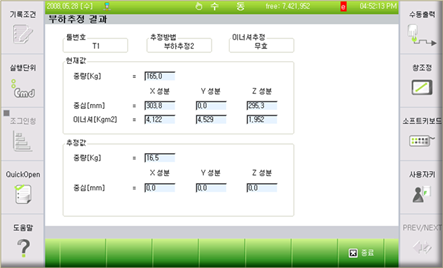
Figure 7.69 Load estimate results
(6) When the above load calculation results are displayed after completing the load calculation program, press the 『[F7]: End』key. It will prompt you with a question to ask whether to reflect the calculation result. When you press the [YES] key, the calculated result is reflected to 『[F2]: System』 → 『3: Robot parameter』 → 『1: Tool data』, and when you press [NO] key, it will not be reflected.
n Tool number
Enumerate the tool on the robot end to use. Hi5 controller can use up to 15 tools ranging 0 ~ 15.
n Estimation method
① No load preparation
On how to create the no load data file, move the robot to a location where there will be no interference with the activity, and press the 『[F7]: Set pose』key and 『[F2]: Play normal』key. To obtain data using load estimate 1, you must have a non-load data file (ROBOT.NL0).
② Load estimation 1
When a no load data file (Robot name, NLD) exists in the internal memory, select load calculation 1 and measure the weight and center of the load by pressing the 『[F2]: Play normal』key. If the no load data file (Robot name, NLD) does not exist, and you pressed the 『[F2]: Play normal』key, a message saying “No load data file does not exist.”, Will be displayed in the guide frame.
③ Load estimation 2
When there is a no load data file (Robot name, NLD) in the internal memory, select load calculation 2 and press the『[F2]: Play normal』key to calculate the weight and center.
n Inertia estimation
This not only calculates the tool load weight and central location, but also the inertia of the tool. Because the robot operates at high speed, always check the operation to see if it is operating without any interference safely to calculate the tool inertia.
n Basic axis start position designation
This designates the starting position of the robot to be used for estimate methods. Move the base axis of the robot to move to a location without interference and press the 『[F7]: Set pose』key to designate the starting position. In order to use the load estimate 1 function, the starting position of non-load preparation must be the same as the starting position
Even though S axis and H axis does not have a position limit, in case of the V axis, the position should be set to -60 deg or above and +60 deg or below, and, when the V axis link is set in parallel to the ground as much as possible, the estimate results will be made better.
As shown in the second following figure, the V axis angle, displayed in the teaching pendant of the Hi5 controller, is the angle against the previous axis, not the angle against the ground surface. For your information, as shown in the first following figure, the V axis of the previous Hi4 controller is displayed after being converted in the angle against the ground surface.

Figure 7.70 [HX165-Hi4 H=40deg, V=0deg, V axis ground surface based angle 0deg]

Figure 7.71 [HS165-Hi5 H=40deg, V=0deg, V axis ground surface based angle -50deg]
The conversion formula in Hi5 controller for the angle of the V axis against the ground surface is as follows.
Angle of the V axis against the ground surface = H axis angle + V axis angle -90 deg
When the 『[F7]: Set pose』key is pressed, while the position is outside range where the angle measured for the V axis against the ground surface is within -60deg~60deg, the message 『The angle of the V axis should be kept within 60 degrees against the ground surface』will be displayed.
The starting position of the write axis is defined automatically to be R2=0.0deg, B=-Vdeg and R1=0.0deg. In other words, R2 and R1 axis is set to 0 deg and the B axis should be set to opposite of V axis to maintain horizontal position.
① Current
It indicates the position of the main axis (S, H, V) of the robot in degrees..
② Designation
When the non-load data file (ROBOT.NL0) exists, the angle of main axis of the robot (S, H, V) is shown.