7.6.9. Robot and tool calibration
7.6.9. Robot and tool calibration
This function is to be used in an environment in which the position of a robot can be measured using by a 3-dimensional measuring device.
(1) Set the position, targeted for the measurement, at the end of the too. While moving the robot in various positions and postures, measurement should be taken at more than 15 points. The positions measured while doing this need to be recorded using the program.
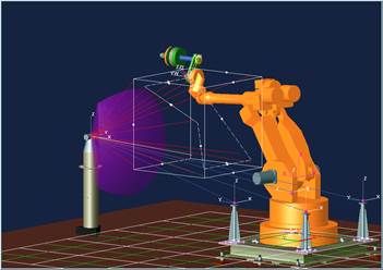
Figure 7.79 Robot data measurement method
(2) The data of the measured points need to be arranged in the X, Y and Z formats and saved in ASCII file format. However, the extension should be *.msr for saving the file. This file needs to be copied and inserted into the teaching pendant using a USB memory
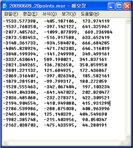
Figure 7.80 Measured robot position data
(3) Access the robot and tool calibration menu and use the explorer key [PF3] to select the relevant msr file.
(4) Select the robot program that was used for the measurement.
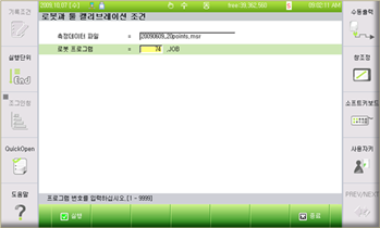
Figure 7.81 Robot calibration data entry
(5) Press the execution key [F7], then, the calibration screen will show up. Then, if you press the execution key [F1], the calibration results will be displayed.
(6) Press the completion key [F7], then the following message will show up. Then, if you select ‘Yes’, the calibrated values will be applied to the axis constant and tool constant automatically
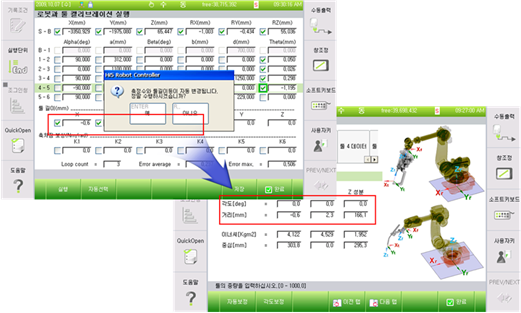
Figure 7.82 Robot calibration execution screen
Information) The basically selected calibration parameters are the axis constants of the H, V, R2 and B axes, as well as the X, Y, and Z values of the tool length. In order to calibrate the tool only, the marked check box for each axis should be unchecked before the execution.