3.7. Input Signal Assignment
3.7. Input Signal Assignment
(1) Select 『[F2]: System』 → 『2: Control Parameter』 → 『2: Input/Output Signal Setting』 → 『3: Input Signal Assign』
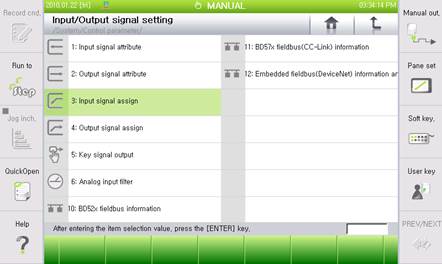
Figure 3.11 I/O Signal Setting Menu
(2) For example, if you want to receive the external Reset signal as #18 Input Signal of CC-Link, enter “5.18” in the edit box and press [ENTER]. “5.18”will automatically switch to “FB5.18”. Now, click on the 『[F7]: Complete』 button to complete the setting.
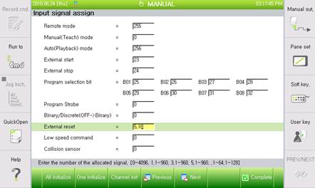

Figure 3.12 Input Signal Assignment
(3) Setting of “0” refers to “Not Assigned” and “1~4096” refers to the “DI/DO (logical input/output)”. “1.n, 3.n” refers to 1, 3 channel of BD52x Fieldbus and “5.n” refers to BD57x CC-Link.
(4) When you click on 『[F1]: All Initialize』 button, all the values of all the signals currently displayed on the screen, will be set to the default value (DI/DO (logical input/output)). When you click on the 『[F2]: One Initialize』 button, only one signal where the cursor is currently located will be reset to the default value (DI/DO (logical input/output)).
(5) When you click on the 『[F3]: Channel init』 button, the text message box of the selected channel number (FB1~FB5) will be displayed. Enter 5 and click on [ENTER] to automatically enter the CC-Link Input Signal for all the input signals.
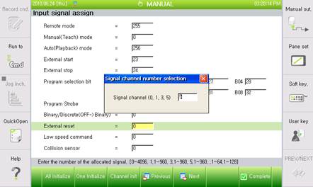
Figure 3.13 Signal Channel Number Selection
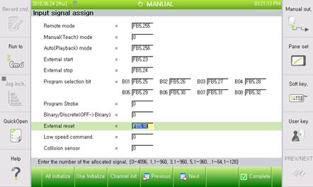
Figure 3.14 Result of Setting to Channel #5 (CC-Link)