3.6. Input Signal Attribute
3.6. Input Signal Attribute
(1) Select 『[F2]: System』 → 『2: Control Parameter』 → 『2: Input/Output Signal Setting』 → 『1: Input Signal attribute』
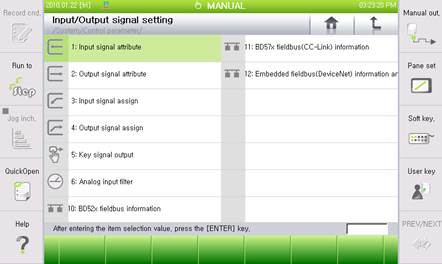
Figure 3.9 I/O Signal Setting Menu
(2) For example, if you want to set the negative logic for CC-Link Input #5, enter “5.12” in the empty block of the signal column. “5.12” will automatically be converted to “FB5.12”. After changing the logic of this item to Negative, click on the 『[F7]: Complete』 button to complete the setting.
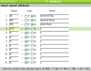
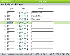
Figure 3.10 I/O Signal Attribute
(3) Setting of “0” refers to “Not Assigned” and “1~4096” refers to the “DI/DO (logical input/output)”. “1.n, 3.n” refers to 1 and 3 channel of BD52x Fieldbus, and “5.n” refers to BD57x CC-Link.
(4) You can set up to maximum of 24 items. To view the next page, click on the 『[F5]: Next』