3.5. System Area of CC-Link
3.5. System Area of CC-Link
When using RX/RY + RWr/RWw mode, you cannot use the last 2 bytes of the usable RX/RY area because they are the system areas.
Table3-13 shows the system area. Of the areas, “Reserved area” currently can be used but will be changed for different usage in the future version of the CC-Link protocol.
Please restrain from using the “Reserved area” as much as possible as it can cause malfunction due to lack of compatibility.
Table 3‑13 System Area of CC-Link
Link input | Signal name | Link output | Signal name | |
RXn0 | Reserved area | RYn0 | Reserved area | |
RXn1 | RYn1 | |||
RXn2 | RYn2 | |||
RXn3 | RYn3 | |||
RXn4 | RYn4 | |||
RXn5 | RYn5 | |||
RXn6 | RYn6 | |||
RXn7 | RYn7 | |||
RXn8 | Initial data processing request flag | RYn8 | Initial processing complete flag | |
RXn9 | Initial data setting complete flag | RYn9 | Initial setting request flag | |
RXnA | Error status flag | RYnA | Error setting request flag | |
RXnB | Remote station ready | RYnB | Reserved area | |
RXnC | Reserved area | RYnC | ||
RXnD | RYnD | |||
RXnE | OS definition | RYnE | OS definition | |
RXnF | RYnF | |||
| Number of stations | 1 | n=1 | |
2 | n=3 | |||
3 | n=5 | |||
4 | n=7 | |||
Because “RXn8~RXnB” and “RYn8~RYnA” use the self-handshake of CC-Link communication, common I/O cannot be used. If you have to use this area inevitably, you must stop the handshake operation of this area of the Hi5 Controller. For this set the system signal option as shown in [Figure 3.8].
But, please avoid this method as it does not satisfy the CC-Link standard.
| If you are utilizing the handshake of RXn8~RXnB and RYn8~RYnA on the PLC side, you must set the system signal to “System”. |

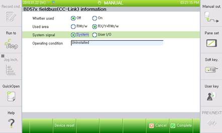
Figure 3.8 System Signal Setting