2.11. Explosive-Proof Scheme
2.11. Explosive-Proof Scheme
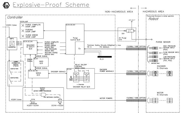
Figure2.18 Explosive Proof Scheme
The explosive-proof system proceeds with the following procedure.
(1) When Controller is power on or reset, Air Purge Process Start.
(2) Monitoring the state of the pressure switch on the Purge control board.
(The EX area of the Purge Control board is intrinsically safe)
(3) When air purge is completed, transmit completion signal to the Sequence & Safety board with TBIO cable and turn on the Relay board.
(4) Then the Sequence & Safety board sends control signals to the Servo board and Servo Drive board to drive the robot.
The Servo board controls the robot’s encoder. For explosive-proof, the Relay board processes the encoder power as a dual channel.
The Servo Drive board controls the robot’s motor. For explosive-proof, the Power Distribution Module (PSM30) consists of two contactors.
Each SMPS converts AC 220V to DC ±5V, DC ±15V, DC ±24V and supplied to each board. SMPS for 5V, 24V is IEC 61010-1 certified. Model Name for 5V is ‘QUINT4-PS 5DC’ and model Name for 24V is ‘QUINT4-PS 24DC’.
(5V on the Main B/D, 5V/15V on the Servo B/D, 5V/24V on the Sequence & Safety B/D and Purge Control B/D, 24V on the Encoder Relay B/D)
For motor control, frequency control of AC is required. So, after changing AC 220V to DC 330V through the converter of the servo drive, the AC frequency is controlled by IPM.