9.2.1. When the pressure of the nitrogen gas container exceeds 150bar
9.2.1. When the pressure of the nitrogen gas container exceeds 150bar
(1) Set the posture of the H-axis of the robot at 90° and cut the power of the controller.
(2) Remove the plug that is installed at the gas inlet of the spring and connect the charging plug.
(3) Check the closed state of the bleed valve ⓟ and shutoff valve ⓠ of the pressure tester.
(Turn clockwise to close)
(4) Turn the knob ⓞ in a counterclockwise direction, careful not to stick out the release pin ⓡ.
(5) Turn the knob ⓝ of the pressure tester clockwise to completely connect it to the gas inlet.
(6) Check whether handle ⓤ and the shutoff valve ⓠ are locked.
(7) Connect the connection section screw of the regulator to the nitrogen gas container screw.
(Connect the hoses as shown in the figure.)
Because the specification for the nitrogen gas container screw varies in different countries, you must purchase a regulator that fits the specification of the nitrogen gas container screw.
If the pressure of the nitrogen gas container is below 150bar, both a regulator and a booster should be mounted. (Conditions for nitrogen gas containers that can be filled up without a booster. : the capacity has to fill the pressure of 150 bars or more and the gas spring pressure of 140 bars.)
(8) Gauge ⓧ shows the set gas pressure and gauge ⓨ indicates the pressure of the nitrogen gas container.
(9) Open the knob ⓩ of the nitrogen gas container, and turn the handle ⓤ of the regulator (ⓥ) to set the gas pressure. (The set gas pressure is specified in Table 9.1 Pressure per temperature.)
(10) Open the shutoff valve ⓠ slowly and charge until the pressure gauge ⓣ reaches the set pressure.
(11) If the set pressure is reached, lock valve ⓠ and then open the bleed valve ⓟ to release the residual pressure inside the pressure tester.
Do not turn the bleed valve ⓟ by more than 360˚.
(12) Close the bleed valve ⓟ to adjust the pressure of the gas spring.
(13) Check the pressure of the pressure gauge T while turning the knob ⓞ slowly in a clockwise direction.
Be careful not to damage the valve installed in the gas string with the release pin R.
(14) When the set pressure is exceeded, repeatedly open and close the bleed valve ⓟ slightly to adjust the gas pressure to the desired level.
(15) Turn the knob ⓞ counterclockwise to retract the release pin ⓡ.
(16) If the pressure has been checked, open the bleed valve ⓟ to completely release the residual pressure inside the pressure tester.
(17) Lock the knob ⓩ of the nitrogen gas container and loosen the connection section of the regulator to separate it from the nitrogen gas container.
(18) Separate the shutoff connection section from the pressure tester.
(19) Turn the knob N of the pressure tester in a counterclockwise direction to separate it from the gas spring.
(20) Check if there is oil or air leakage in the check valve of the gas spring.
Warning! Do not look into the check valve hole directly while gas is charged in the gas cylinder.
(21) Install the G1/8 plug to the gas spring.
After charging gas, wait for 30 minutes until the temperature comes back to room temperature, and then use it.
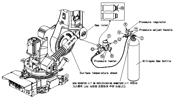

Figure 9.2 Charge Gas into the Gas Spring
| As the shape and name of the gas supplement kit may vary depending on the type, refer to the accompanying manual. |
