7.3.8. Collision detection (of each axis) setting
7.3.8. Collision detection (of each axis) setting
Collision detection function is to minimize the damage from collision during robot operation. It compares the currently generated torque with the normal torque of the robot and when an abnormal torque is generated from the robot, it sends out an error message.
Hi5a controller increases the safety of the robot by mutually supplementing the collision detection function to the existing over-current, overload, over speed and location deviation error detection function as the safety device when the robot is operating in an abnormal condition or malfunctioning.
The collision detection function monitors the disturbance torque generated from each axis and the disturbance torque rate, and sends an error when the measured value exceeds the set value.
l 『E0160 (○ axis) Collision detected』when the disturbance torque exceeds the set value.
l 『E0161 (○ axis) Impact detected』when the disturbance torque rate the set value.
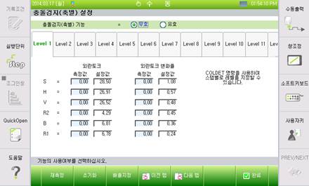
Figure 7.67 Collision detection (of each axis) setting screen
n Collision detection
Select whether to use the collision detection function. But, the collision detection function only applies to the robot main unit and not to the additional axis.
You might have to adjust the detection level according to the installation location or environment, and for the step that requires high sensitivity for collision detection, you will have to adjust it very accurately. Even with the collision detection function enabled, it will not operate during GUN squeeze force. Collision detection function operates only while the robot is moving and does not operate when the robot is in stopped condition.
n Setting items
Select whether it is the disturbance torque or the rate of change of the disturbance torque that will be displayed on the screen. .
n Measured
This displays the maximum values of the disturbance torque and the rate of change of the disturbance torque that are generated in the section where the collision detection (COLDET) command is enabled.
The user can refer to these values to set the disturbance torque and the rate of change of disturbance torque for each level.
n Level
If the detection level or collision detection function, which is used in the jog operation or the step forward/backward operation in manual mode, is enabled, Level 1 will be applied as a default. The user can set the detection level in the program, and the commands that can be used are as follows.
COLDET level
The level can be set as 1 ~ 16. In case of the axes for which 0.0 is set, collision detection will not be performed.
Set level is valid until the next COLDET command is executed.
For example, when the collision detection function is enabled and the work program is as follows
S1 MOVE
S2 MOVE
COLDET 2
S3 MOVE
COLDET 0
S4 MOVE
S5 MOVE
S6 MOVE
END
Step S1 and S2 are detected in level 4 and S3 with level 1. S4, S5 and S6 do not detect collision.
n 『F1: Re measure』
Measure the values of the individual axis disturbance torque and the rate of change of the disturbance torque (Maximum value) again.
n 『F2: Initialize』
Set to initialize the values of all the set levels of individual axes. .
n 『F3: Rate set.』
Quickly set the values of the error detection levels of all the axes for each selected level, by applying the magnification based on the measured value.

Figure 7.68 Magnification selection and entry screen