7.3.1. Tool data
7.3.1. Tool data
This function is for setting the distance and angle of TCP (Tool Center Point) based on the robot’s R1 axis flange and also the registered tool weight, center of gravity, and inertia. In this screen, the user can can input these values manually.
In other setting methods, the tool length can be set by using the “auto calibration” function, and the tool weight, center of gravity, and inertia can be registered by using the load estimation function.
Before teaching, the tool length and angle should be set accurately. This is because when linear or circular interpolation is performed, the trajectory will be created based on the TCP.
Hi5a controller is controlled based on the robot dynamics. The weight, inertia and center of the tool must be set accurately for the robot to operate quickly and safely. When this value is incorrect, it can cause serious problems to the performance and life of the robot.
Especially if you are using the tool change function, you must allocate a separate tool number not just for the condition in which the tool is separated but also for the information of each tool to enter and use the tool information for the tool change function.
Also for the handling of heavy objects, each tool number must be allocated for the attach/detach condition of the object for use.
Tool length is the length by each direction in the flange coordinate system shown as follows.
(1) Distance in X axis : Xt
(2) Distance in Y axis : Yt
(3) Distance in Z axis : Zt
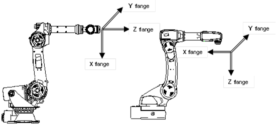
Figure 7.55 Flange coordinate system by robot type
Tool angle is the amount of position change in each direction in the flange coordinate system.
(1) Angle in X axis : Rx
(2) Angle in Y axis : Ry
(3) Angle in Z axis : Rz
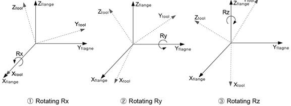
Figure 7.56 Tool angle
Therefore, the tool distance and angle is set based on the flange coordinate. Tool distance is the set between the center of the flange coordinate and TCP.
The tool position is the rotated values of X, Y and Z axis direction in reference to the tool flange coordinate according to the set tool angle.

Rxyz = Rot(z,Rz)Rot(y,Ry)Rot(x,Rx)
Rxyz is the tool position rotation matrix based on tool flange
Rot(z,Rz) is the rotation matrix that shifted by Rz to the Z axis direction of flange coordinate
Rot(y,Ry) is the rotation matrix that shifted by Ry to the Y axis direction of flange coordinate
Rot(x,Rx) is the rotation matrix that shifted by Rx to the X axis direction of flange coordinate.
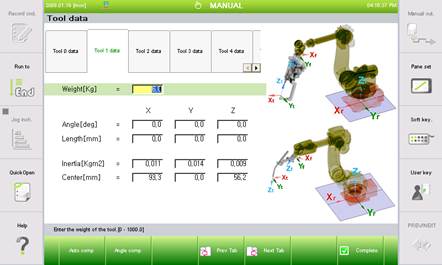
Figure 7.57 Tool data setting screen
n Weight (Kg) : Weight of tool
n Angle(deg) : Angle of Tool.
The “auto calibration” or 『[F2]: Angle calibration』function can be used.
n Length (mm) : Length of Tool.
The “auto calibration” or 『[F1]: Auto calibration』function can be used.
n Inertia (Kgm2) : Tool inertia for the tool coordinate
You can use the “load estimation function”.
n Center (mm) :Weight center location of the tool based on the flange center
You can use the “load estimation function” .

l In some cases, when the cursor is moved to the angle or length input box and date is entered, the guide frame could display the “Please, consult the engineer” message. When this is shown, press the 『[F1]: Auto calibration』or『[F2]: Angle calibration』key. Refer to the following content for auto calibration and angle calibration.
l Automatic calibration
① If you locate new tool for setting to the step location where existing step was, and then the distance and the angle for the new tool is calculated.
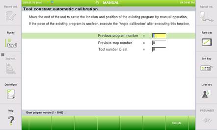
Figure 7.58 Tool constant automatic calibration screen
n Previous program number
Enter the program number taught before the tool change.
n Previous step number
Enter the step number to execute tool constant auto calibration.
n Tool number to set: Enter the tool number to newly set.
② Through the automatic calibration function, you can easily generate the tool data and also use the existing program as it is.
l Angle calibration
This function calibrates the tool angle.
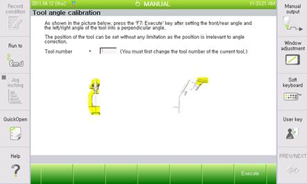
Figure 7.59 Tool angle calibration screen