2.2. Sealing Settings
2.2. Sealing Settings
The sealing settings menu sets parameters for the different signal specifications and operating environment required for this function. This menu is only displayed for the sealer axis.
“[F2]: System” → “4: Application parameter” → “20: Sealing settings”
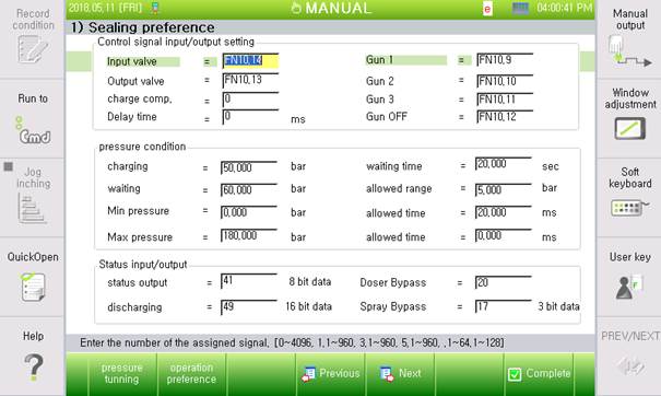
Figure 2.2 Sealing settings
(1) Input/output valve
Input and output valve signals are output allocation signals to output the open/close signal of the input/output valve of the booster to DeviceNet. If input/output valve signals are not set as essential input signals, the operation of the sealer axis will be limited.
The filling-complete signal is an input allocation signal for the robot controller to receive the signal from the booster when the cylinder reaches the filling-complete position. If it is not set, the filling state is determined when the pressure reaches the filling pressure after moving to the filling-complete position.
The operation delay is a setting to operate the cylinder after waiting for a specified time after outputting a valve signal.
For the gun signal, specify the corresponding valve signals for individual guns if the system has a 3-D gun that has three nozzles. If not, enter “0.”
(2) Pressure condition
Filling pressure is a reference to wait for filling until a pressure above the set pressure is detected at the filling-complete position if the filling-complete signal is not set. An error will be detected if the measured pressure does not meet the filling-complete condition during filling-pressure waiting time.
For the waiting pressure, enter a pressure to keep while waiting after filling the sealer. Enter a pressurization adjustment tolerance.
For the minimum and maximum pressures, set references to protect the sealing equipment. If an excessive or poor pressure is detected over the allowed time, an incorrect pressure error will occur.
(3) State input/output
Allocate the state output signal for the robot controller to send out the operation state of the booster (“Standstill,” “Pressurizing,” “Pressurized,” “Discharge,” “Filling,” and “Waiting pressure adjustment”). If the state output signal is set to “0,” the current state is not outputted; 8-bit output state data is consecutively outputted from a specified output signal port. However, the top bit is outputted if the booster is full with the sealer solution.
MSB:B7 | B6 | B5 | B4 | B3 | B2 | B1 | LSB:B0 |
Full | reserved | - | - | Dozer state | |||
B3 | B2 | B1 | B0 | State |
0 | 0 | 0 | 0 | Standstill |
0 | 0 | 0 | 1 | Pressurizing |
0 | 0 | 1 | 0 | Pressurized (Pulse) |
0 | 0 | 1 | 1 | Discharging |
0 | 1 | 0 | 0 | Filling |
0 | 1 | 0 | 1 | Adjusting the atmospheric pressure |
The discharge-amount output signal is outputted as an integer data without a code by multiplying the volume of the discharged sealer solution (in cc) through 16-bit data with 100. That is, the discharged amount can be calculated by dividing the received data with 100 on the receiving side.
However, the calculated discharge amount is a simple calculation using the current cylinder position from the filling-charge position; thus, it may be different from the actual discharge.
The Dozer Bypass signal is an emergency action for booster failure, and it is used to receive the operation state of the dozer bypass to bypass the booster and directly discharge the sealer solution from the pump. The dozer bypass mode does not allow the booster control motor to move; thus, the pressure and discharge amount cannot be controlled. It controls the open/close signal only for application; thus, the quality is not guaranteed.
The Spray Bypass signal is a 3-bit input signal to receive the operation state of the spray bypass mode to check the robot motion route only without applying the sealer solution. For 3-D guns with three nozzles, the spray bypass mode can be individually set for the guns.