3.2. Work scenario
3.2. Work scenario
Laser welding can be performed in two modes. The first mode is STATIC mode, in which the laser is emitted while the robot is stationary. The mode can be used only when the welding points are within the scanner emission range. Therefore, it is not actually used well for the panel welding for cars. The second mode is the OTF (On-The-Fly) mode, in which the welding of the pre-stored welding points are to be carried out while the robot moves. The mode is mainly used for the BlackBird laser welder. In the OTF mode, there is a recording file in which welding points are grouped into an arbitrary group, and the start and end of the group are stored as a trigger signals. While the welding is carried out, the trigger signal of the recording file will be compared with the actually inputted trigger signals in order to determine the welding point and position. For OTF mode welding, it is required to make the laser controller move the robot over the welding points one by one so that the laser controller can store the welding points. Since the robot position value is sent via DeviceNet communication, no special operation for storing is needed. In the next step, it is required to execute a motion program for the robot to move in the real welding work. In this process, the robot will not move over all the welding points that have been taught, but will move in continuous motion approximately within the laser scanner emission range. Note that this motion program should include the trigger signal to display the welding section and the command (UDPsnd) to send data. When the welding program is performed actually, the status of the laser welder will be checked, and the JOB program will be executed again in continuous motion approximately within the previously written welding points. Whether the robot motions and trigger signals created when the recording file is written are matching with those created when the actual welding is performed is a critical factor in improving the quality of welding. The following figure shows a scenario for a work on a new work panel that should be performed by the robot controller and laser controller.
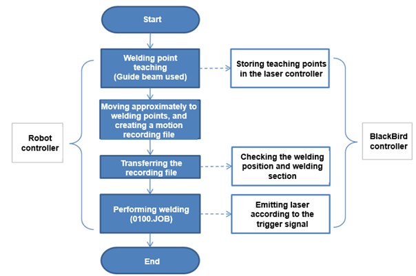
Figure 5 Work scenario


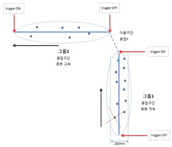
Figure 6 Welding points and robot moving path
- Teaching of welding point is carried out based on the intersection point of the cross-shaped guide beam.
- The working area of the laser scanner is 220X220X140mm.
- The welding motion speed is 100 ~ 200mm / sec but it is getting faster to shorten the work time
- Movement will take place in linear motion in the welding section, while joint motion is also possible in the section where no welding work is carried out.
- The welding group can be arbitrarily set by the user and distinguished using the trigger signal.
- Since the trigger signal is basically in the active LOW mode, the welding will be performed only in the OFF section.
(The signal for the welding section should be set to ‘Off’ when writing the motion program)
- The recording file must be both started and ended with the trigger signal On to ensure that the recording file can be loaded normally.