2.1. BD525 DeviceNet Mastersetting
2.1. BD525 DeviceNet Mastersetting
To set the network of the master of the BD525 DeviceNet, execute according to the following procedures. Sycon.net and the USB driver must be installed first before setting the DeviceNet network.
(1) Install the EDS file of the slave unit that needs to be installed to the master of the BD525 DeviceNet.
- Execute Network > Import Device Description
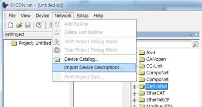
Figure 2.1 Sycon.net Import Device Description Menu
- In the Import Device Description dialog box, select "DeviceNet EDS" as the file type. After that, select the EDS file of the system that needs to be installed, and click the Open button.
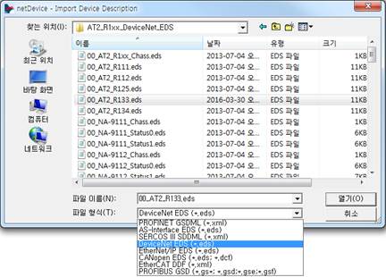
Figure 2.2 Installation of the Sycon.net EDS file
(2) Configuration of the DeviceNet network (insertion of the master and the slave)
- In the Device Catalog window, drag and drop "NETX 100 DN/DNM" into the bus line of the DeviceNet window.
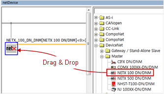
Figure 2.3 Insertion of the master
- In the Device Catalog window, drag and drop the slave units, which are to be connected, into the bus line. (This stage can be skipped when it is required to search the slaves connected to the master by scanning the network. Refer to (5) Slave Search.)
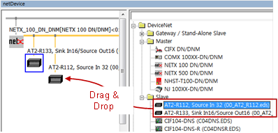
Figure 2.4 Insertion of the slaves
(3) USB-based connection between the BD525 board and Sycon.net
Connect the PC, in which Sycon.net is installed, and the BD525 board using a USB cable. If the USB driver is normally installed, you can see NETX 100 in Devices and Printer (in case of Windows 7).

Figure 2.5 USB Device
(4) Setting of the master connection driver
Open the DTM setting dialog box by double-clicking the master (NETX 100 DN/DNM) icon, and execute the following in sequence.
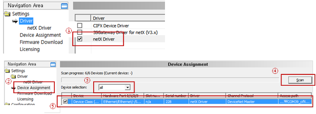
Figure 2.6 Setting of the master USB driver
① In Navigation Area, select Setting > Driver. Then, check the check box of the NETX Driver in the list of drivers on the left before clicking the Apply button.
② In Navigation Area, select Setting > Device Assignment.
③ In the Device Assignment screen on the right, change the Device Selectionto "All".
④ Click the Scan button.
⑤ In the list of devices, check the check box of the DeviceNet masterunit, and click the Apply button.
(5) Searching of a slave (Skip this stage when a slave was added manually in Stage (2).)
- Right-click the Master icon, and select the Connect menu.

Figure 2.7 USB communication connection
- When the USB connection is normal, the Master icon will turn green.
- Right-click the Master icon, and select the Network Scan menu.

Figure 2.8 Scanning of the network
- Of the searched slave nodes, change the Action of the devices that need to be added to the DeviceNet network to "Add," and click the Create Devices button.
∙ Action è Add : Adding a new node
∙ Action è Skip: No additional nodes.
∙ Action è Replace: Changing to the searched node
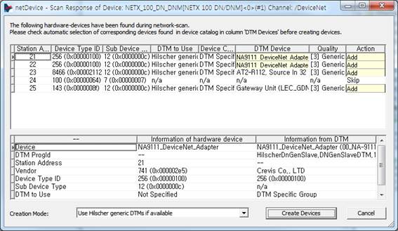
Figure 2.9 Dialog box for the network scanning result
- In the dialog box asking whether to override the existing module setting, if you click the Y button, the relevant node will be added.
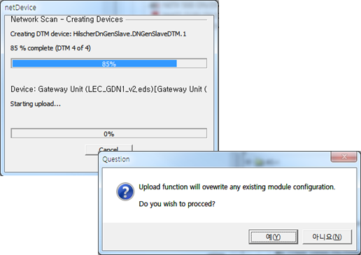
Figure 2.10 Adding a node after scanning the network
(6) Setting of the slaves
- To be set when it is required to change the settings of the slaves searched through the Network Scan function or to configure the DeviceNet network manually
- Double-click the Slave icon to open the setting dialog box.
- In Configuration of Navigation Area, select Connection, and select a method to connect the DeviceNet.

Figure 2.11 Setting of the method to connect the slave of the DeviceNet
- In Configuration of Navigation Area, set the sizes of the input and output data, as well as the items related to the cycle of communication, for the set connection method.
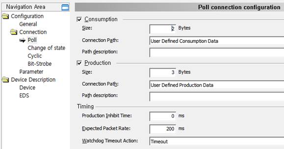
Figure 2.12 Setting of the connection of the slaves
※ Refer to the Generic Slave DTM for the DeviceNet Slave Devices manual for details related to the setting of the slaves.
(7) Setting of the master
- Open the Settings dialog box by double-clicking the Master icon..
- BUS parameters, such as the MAC ID, communication speed, and options for handling errors, can be set by selecting Configuration > BUS ParametersNavigation Area.
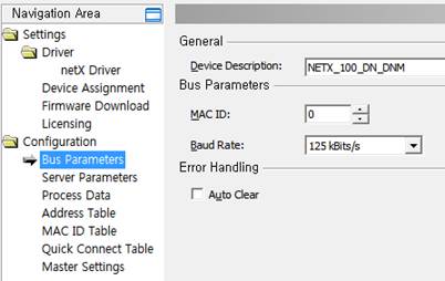
Figure 2.13 Setting of the master
Bus Parameter | Description | |
MAC ID | This is the address of the master of the DeviceNet. (Allowable scope: 0~63) | |
Baud Rate | This is the communication speed of the master of the DeviceNet. (Allowable scope: 125Kbps, 250Kbps, 500Kbps) | |
Auto Clear | Check | If there is a communication error with any of the slaves, the operation of the master will shift from the Operate mode to the Clear mode, cutting off communication with all the slaves. It is required to reset to recover this state (either to reset or use the power of the controller . ONè OFF è ON). |
Deactivation | Even when there is a communication error with any of the slaves, the operation of the master will stay in the Operate mode, maintaining communication with the connected slaves and the ones that have a communication problem. | |
Table 2‑1 DeviceNet Master BUS Parameter
- The BD525 DeviceNet master can play the roles of the master and the server (slave) at the same time. To the use the function as a DeviceNet server, select Configuration > Server Parameters in Navigation Area, and select the I/O Connection information.
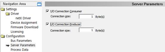
Figure 2.14 Setting of the master server parameter
∙ I/O Connection Consumer: Check the check box of the use, and input the size of the output data (consume connection size) as a slave by taking another master as reference. (0~255)
∙ I/O Connection Producer: Check the check box of the use, and input the size of the output data (consume connection size) as a slave by taking another master as reference. (0~255)
- The option to start communication can be selected by selecting the master of the Navigation Area Settings dialog box.
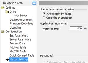
Figure 2.15 Master settings
Start of bus communication | Description |
Automactically by device | Communication will start automatically when the initialization of the BD525 DeviceNet is completed. |
Controlled by application | The main software of the controller performs controlling to start communication. When this option is set, the Network Scan function cannot be used. |
Table 2‑2 Option of starting communication
- The MAC ID Table, Process Data, Quick Connect Table, and others can be set. Refer to the DTM of the DeviceNet Master Devices manual for more details.
(8) Download
- When all settings are completed, connect by right-clicking the Master icon, and select Download.

Figure 2.16 Setting of the master download
(9) Setting of the master of the BD525 DeviceNet of the robot controller
- Execute "[F2]: System" →"2: Control parameter" → "2: Input and output signals setting" → "15: BD525 fieldbus setting and diagnosis."
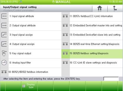
Figure 2.17 Menu of the BD525 fieldbus setting and diagnosis
- When there is an error with the sizes of the input and output data or with the communication, select the option of input handling, and click "[F6]: Apply" or "[F7]: Complete" button.
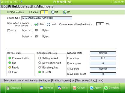
Figure 2.18 Setting and diagnosis of the BD525 fieldbus master