8.2 Touch sensing function
8.2 Touch sensing function
Touch sensing is a function used to detect the position of the workpiece and the start point or welding end point.

Figure8.4 Example of Touch Sensing
The workpiece is not always in a fixed position because of the error in the jig or positioner and the variation in the gaps of workpieces. Considering this, touch sensing can be used to detect the welding start point and welding end point to carry out welding.
Alternatively, if the reference position is recorded through touch sensing, it will be possible to calculate how much shift is made from the reference position when the workpiece enters. A function that automatically calculates and compensates these shifts can also be used.
In touching sensing, eight types in total (Fillet, VGroove, Butt, LRCen, AP Fillet1, AP Fillet 2, DetectGroove, and Wall) will be supported, as shown in Figure 8.12.


Figure8.5 Touch Sensing Type
There are eight conditions in total for touch sensing. If you press Quick Open in the command, the edit screen will appear, as shown in Figure 8.13. The edited contents related to the search speed, retraction speed, search distance, progress distance, error compensation amount, touch method, etc. will be stored in the ROBOT.TSC file.
.


Figure8.6 Touch Sensing Condition Edit Screen
The touch sensing command can be recorded by inputting “command input” – “Arc” – “TOUCHEN” on the TP screen. The command can be configured as follows.
TOUCHSEN TSC#= Condition number, Search direction 1, Search direction 2, Search direction 3, Calculated pose, Butt gap variable
TOUCHSEN TSC#= Condition number, Search direction 1, Search direction 2, Search direction 3, Angle of search direction, Calculated pose, Butt gap variable
TOUCHSEN TSC#= Condition number, Search direction 1, Search direction 2, Search direction 3, Angle of search direction, PAR=Pose shift number, Butt gap variable
TOUCHSEN TSC#1, +TX, +TZ, 3, P10, V1!
TSC#1 : Touch sensing option number (index number corresponding to the conditions of the ROBOT.TSC file)
+TX, +TZ : Search direction parameters (orthogonal, pose, tool coordinate and, tool projection can be inputted)
3 : Amount to lift after touching the bottom (mm) (Butt, VGroove), Detection reference distance (DetectGroove).
P10 : Pose variable to store the pose calculated through sensing
V1! : Variable to store the gap of the workpiece for the butt operation (rounded to the first decimal place)
QuickOpen key : Search speed, retraction speed, search distance, progress distance, error compensation amount, and touch type (upon contact or upon contact release) can be designated.
The sensing direction can be designated as follows according to the workpiece type.
Fillet : Base coordinate direction, Pose direction, Tool projection direction, +TZ direction
Butt : Pose direction, Tool direction
V Groove : Pose direction, Tool direction
LRCen : Tool direction
AP_Fillet : Tool projection direction
DetectGroove: Tool direction, Tool projection direction
Wall : Orthogonal direction, Tool direction, Tool projection direction
Type | Maximum number of search directions | *Orthogonal X, Y, and Z shall be supported for all types* | Tool coordinate | Tool projection coordinate | Pose | Other input parameters |
Fillet | 3 | O | O (1 touch point) | O | O | Retraction distance |
Butt | 2 | X | O | X | O | Error compensation amount |
VGroove | 2 | X | O | X | O |
|
LRCen | 1 | O | O | X | X |
|
AP_Fillet | 2 | X | X | O | X | Progress distance 1 and 2 |
AP_Fillet2 | 2 | X | X | O | X | Progress distance 1 and 2 |
DetectGroove | 2 | X | O | O | X | Progress distance 1, Retraction distance 1 |
The following is an example based on the assumption that the workpiece type is designated as a fillet for the first condition for touch sensing, but for the second condition, and V groove for the third condition (the conditions set by the user with Quick Open in the command).
TOUCHSEN TSC#=1, TF, TD, 0, P10, 0 #1 condition, Tool projection direction, Two-point touch
TOUCHSEN TSC#=1, +X, -Y, -Z, P10, 0 #1 condition, Base coordinate direction, Three-point touch
TOUCHSEN TSC#=1, P1, P2, 0, P10, 0 #1 condition, Pose direction, Two-point touch
TOUCHSEN TSC#=1, +TZ, 0, 0, P10, 0 #1 condition, +TZ direction, One-point touch
TOUCHSEN TSC#=2, +TX, +TZ, 3, P10, V1! #2 condition, Tool coordinate direction, Ascending 3 mm after touching the bottom
TOUCHSEN TSC#=2, P1, P2, 2, P10, V1! #2 condition, Pose direction, Ascending 2 mm after touching the bottom
TOUCHSEN TSC#=3, -TY, +TZ, 3, P10, 0 #3 condition, Tool coordinate direction
TOUCHSEN TSC#=3, P1, P2, 3, P10, 0 #3 condition, Pose direction
The touch sensing methods (workpiece types) to be provided are as follows.
[1] Fillet type
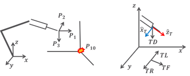
Figure8.7 Example of Touch Sensing – Fillet Type
TOUCHSEN TSC#=1,P1,P2,P3,P10, 0
TOUCHSEN TSC#=1,+X,-Y,-Z,P10, 0
TOUCHSEN TSC#=1,TF,TD,0,P10 0
TOUCHSEN TSC#=1,+TZ,0,0,P10 0
• Tool projection method: A method of determining the forward, left, right, and down directions by projecting the Z-axis of the tool coordinate system onto the base XYZ plane. The combination of TF (forward), TD (down), TL (left), and TR (right) is used.
TL is TF*RotZ(90) direction, and TR is TF*RotZ(-90) direction.
• If there are too many welding points, making it difficult to manage pose variables, the tool projection method (TPM) can be used
• In the case of a twisted fillet in which the workpiece has a rotation amount (RX, RY, and RZ), the angle designation option can be used to change the search direction.
• For one-point sensing, only one search direction will be designated, and for the two-point sensing, two search directions can be designated, sequentially.
[2] V Groove type
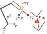
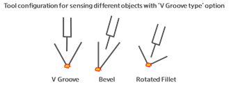
Figure8.8 Example of Touch Sensing - V Groove Type
V Groove type can be used for V Groove sensing. However, the position and direction of the tool should be positioned on a bisector, similarly shown in the figure.
TOUCHSEN TSC#=3, -TY, +TZ, 3, P10, 0 #3 condition, Tool coordinate direction
TOUCHSEN TSC#=3, P1, P2, 5, P10, 0 #3 condition, Pose direction
• It will provide stability to have at least an ascending amount of 3 mm for sensing.
[3] BUTT type
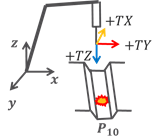
Figure8.9 Example of Touch Sensing – Butt type
TOUCHSEN TSC#=2, +TX, +TZ, 3, P10, V1! #2 condition, Tool coordinate direction, Ascending 3 mm after touching the bottom
TOUCHSEN TSC#=2, P1, P2, 5, P10, V1! #2 condition, Pose direction, Ascending 5 mm after touching the bottom
• For the BUTT type, it is important to position the tool perpendicular to the bottom surface, as shown in the figure.
• It will provide stability to have at least an ascending amount of 3 mm after the bottom sensing is performed for sensing.
•Depending on the ascending amount, the size of the butt gap may change. In this case, it is required to input the error compensation amount in Quick Open in the command, making it possible to calculate the butt gap by subtracting the error compensation amount.
Touch sensing will progress according to the following sequence.
For the Fillet type, the welding start point will be calculated by repeating the process of “Forward → Return” in the orthogonal, pose, tool projection, and tool coordinate directions, depending on the four options. In the case of the Butt or V Groove type, sensing will be progressed as follows. (Upper left and right sensing → Bottom sensing → Ascending → Lower left and right sensing)

Figure8.10 Touch Sending Sequence – Butt Type
For V Groove and Butt types, the point lowered in the workpiece direction from the lower left and right sensing midpoint will be the pose. In the case of DetectGroove type, the process of “Lower sensing → Ascending as much as the ascending amount →Forward” will be repeated. If the point is lowered than the detection reference designated by the user, the descending operation will stop in the middle of the lower sensing process.
Pressing Quick Open in the touch sensing command will make it possible to edit the touch sensing conditions for the relevant condition number TSC#.
• Search distance: This refers to the distances in the search direction. If a workpiece is not detected when it reaches the distance, an error will occur.
• Search speed and retraction speed: The speed for searching or retracting can be designated.
• Error compensation amount: This will be used for compensating the butt gap.
• Retraction distance: In the case of the Fillet type, this refers to the distance to retract after sensing and the distance to lift after touching the bottom in case of the DetectGroove type.
• Point of time for sensing: Supports the “Upon contact” and “Upon contact release” modes. In general, the sensing in “Upon contact” mode is much used and has nearly no error. Only in a case, that sensing shall be performed, considering slight errors because of wire bending during the sensing process, the method of sensing during the retraction will be used.
The angle designation option makes it possible to designate the angle of the search direction. The angle designation option will be supported for the Fillet and DetectGroove types. The angle designation option makes it possible to rotate all the movement trajectories in the sensing sequence on one of the TL axis and base X, Y, and Z axes.
Figure 8.18 shows an example of rotation on the Y-axis or TL axis for the Fillet or DetectGroove type workpiece.
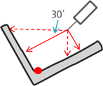
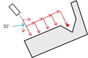
Figure8.11 Example of Touch Sensing – Angle Setting
TOUCHSEN TSC#=1, +X, -Z, 0, Y30, P100, %V1!
TOUCHSEN TSC#=1, +X, -Z, 0, TL30, P100, %V1!
TOUCHSEN TSC#=2, TD, TF, 5, Y30, P100, %V1! ‘DetectGroove
TOUCHSEN TSC#=2, TD, TF, 5, TL30, P100, %V1!‘DetectGroove
The workpiece type and the angle rotation axis to be designated according to the coordinate designated for the sensing direction designated in the command are as follows.
Type | Coordinate designated for the sensing direction | Axis designated for angle |
Fillet | All coordinates | Orthogonal X, Y, and Z axes. TL axis |
Detect Groove | Tool | Impossible |
Tool projection | Orthogonal X, Y and Z axes. TL axis |
The following description shows how to use touch sensing that interworks with the Master/Execution mode.
In Master mode, the sensing pose will be stored in the pose number that corresponds to the PAR number. In the Execution mode, the current sensing pose will be compared with the sensing pose calculated in the Master mode to calculate the shift amount, which will be recorded into the shift variable, corresponding to the PAR number.
TOUCHSEN TSC#=1, +X, -Z, 0, X0, PAR=10, %V1!
PAR stands for Pose and Shift and is used to assign the number for the shift variable. In the command shown above, the sensing pose will be stored in the P10 pose variable in the Master mode, and when sensing occurs in the Execution mode, the shift amount in comparison with the Master mode will be automatically calculated and stored in RO.