8.1.1. Arc sensing condition
8.1.1. Arc sensing condition
On the second screen of the weaving file condition editing screen, the arc sensing condition will be displayed as below. This is for adjusting the setting of the arc sensing that can be used during the weaving operation.
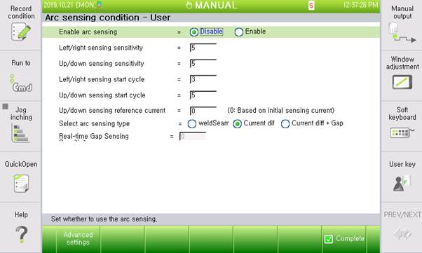
Figure8.1 Arc sensing condition – User dialog box
The setting and operation methods for individual options are as below.
(1) Arc sensing function activation: <Disable, Enable>
Sets whether to use the arc sensing function
(2) Left/right sensing sensitivity: [0–10]
Sets the sensing sensitivity in the left and right directions on the weaving surface
(3) Up/down sensing sensitivity: [0–10]
Sets the sensing sensitivity in the upward and downward directions on the weaving surface
(4) Left and right direction sensing start cycle: [0 ~ 9]
Set the cycle for starting the sensing in the left and right directions on the weaving surface
(5) Up/down sensing start cycle: [Left/right start cycle+1 to 10]
Sets the cycle of starting the up/down sensing on the weaving surface
(6) Up/down sensing reference current: [0–3,000]
Sets the reference current when performing the up and down sensing; this setting adjusts the torch height; if it is set to 0, the average value of the initial section current will be the reference. When it is set to 0, torch collisions could occur because of the inaccurately high initial current if there is a tack welding area.
(7) Arc sensing type selection: <Welding line, current difference, current difference + Gap>
Selects the welding line follow-up method; the welding line mode is to be selected if the accurate right angle fillet welding and asymmetric sensing will be used. In the general symmetric arc sensing, the current difference mode will be used. The current difference + gap mode will be used if the width needs to be adjusted automatically in the middle of welding.
(8) Real-time gap sensing sensitivity: [0–10]
Sets the width variation sensitivity for using the current difference + gap method; it is required to set an appropriate value according to the level of the bead quality and width variation
If you press F1 in the Arc Sensing Condition - User dialog box, the following Arc Sensing Condition - Engineer dialog box appears. This dialog box can only be edited by the engineer.
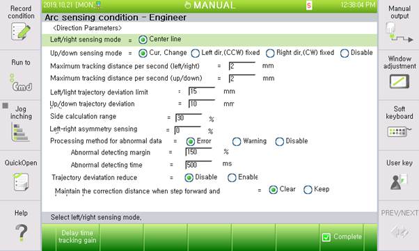
Figure 8.2 Arch sensing condition - Engineer dialog box
The setting and operation method for each item is as follows.
(1)Up/down sensing mode: <Current variation, Wall direction (CCW) fixing, Non-wall direction (CW) fixing, Disable>
Sets the method to perform the up/down sending
- Current variation: Performs height sensing by taking the sensing initial reference data average as the reference
- Wall direction (CCW) fixing, Non-wall direction (CW) fixing: When looking in the direction of the torch moving forward, and if one side is fixed and the deformation occurs only on the other side, then the height sensing will be performed according to the movement amount based on the relationship between the left/right compensation amount and fixed surface.
- Disable: To be selected only when performing only the left/right sensing for the flat arc sensing in which the up/down sensing is not required or cannot be performed
(2)Maximum compensation distance per second (Left/right, Up/down): [0.1–20.0] mm
Sets the maximum distance that can be followed up for 1 s; if you set the value as 10 in the user dialog box, a follow-up will be performed by considering the maximum compensation distance set here.
(3)Left/right and Up/down sensing trajectory deviation limit: [0 ~ 200]
Sets the arc sensing follow-up distance limit value in the left/right and up/down directions; if a follow-up is performed, exceeding the limit distance set by arc sensing, the operation will stop because of an error.
(4)Left/right asymmetric sensing ratio: [-40 to 40] %
Sets the asymmetric sensing ratio to perform sensing by considering the difference, if any, in the width of the beads
(5)Abnormal data handling method: <Error, Warning, and Disable>
This is a method to handle a case in which the normal current range, calculated based on the “abnormality determination margin,” is exceeded for a duration longer than the “abnormality determination time.”
Error: The robot displays an error and stops.
Warning: The robot displays a warning and continues working.
Disable: The robot continues to work.
(6)Abnormality determination margin: [100–200] %
Sets a range to determine abnormality by using the five previous units of data
(7)Abnormality determination time: [10–1000] ms
Sets the time to allow the current input that exceeds the abnormality determination margin; if the margin exceeded beyond this time, the robot will operate according to the relevant handling method.
(8)Trajectory deviation decrease: <Disable, Enable>
Sets whether to ignore the compensation amount of the relevant count when the sensing data is abnormal; if this option is “Enable,” and if the data has severe noise, the previous compensation amount will be sustained.
(9)Sustaining the compensation distance for the step forward/backward: <Clear, Sustain>
Sets whether to sustain the compensation amount when making the robot step forward or backward in the arc sensing or in the multipass operation section; when it is set as Clear, the arc sensing compensation amount will be cleared when the robot steps backward.
When you press F1 in the Arc Sensing Condition - Engineer dialog box, the Data Delay and Follow-up Factor Table dialog box will be displayed as below. The contents of this dialog require our engineering.
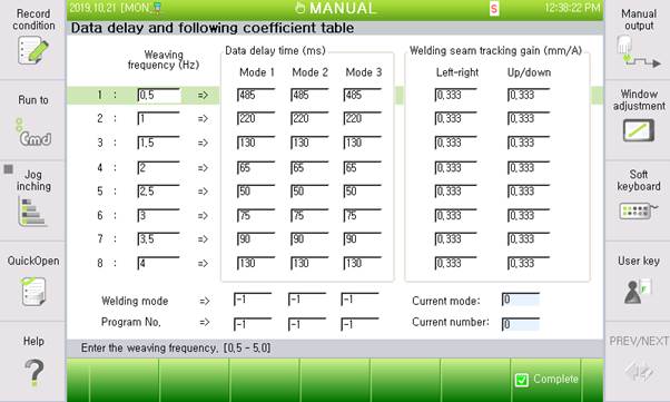
Figure 8.3 Arch sensing condition - Engineer dialog box
Please refer to the ‘Arc sensing function manual’ for details of Arc sensing