8.3.1. Height sensing condition
8.3.1. Height sensing condition
While in the “HSensON AVC#=??” command, press the [QuickOpen] key to enter the 『Height sensing condition』setting screen. The condition setting screen is as shown below.
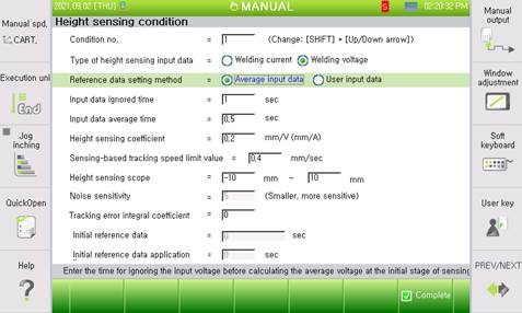
Figure8.13 Height sensing condition dialog box (average input data)
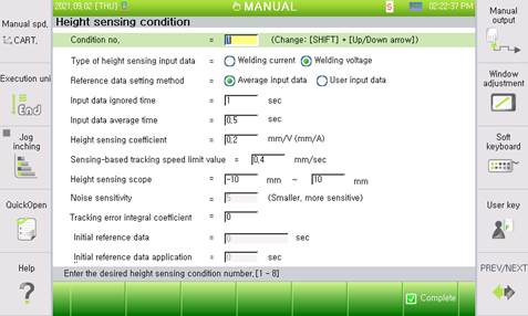
Figure 8.14 Height sensing condition dialog box (user input data)
The methods for setting and operating individual options are as below.
(1) Condition number: [1 ~ 8]
Sets the height sensing condition number.
(2) Height sensing input data type
Indicates the input data type. Welding current will be used for GMAW welding, and welding voltage will be used for TIG welding.
(3) Reference data setting method: <Average input data, User input data>
Selects the reference data setting method.
- Average input data: Set based on the reference data average at the initial sensing stage.
- User input data: Users enter the reference data directly.
(4) Input data ignore time: [0.0 ~ 5.0]
This is the time during which the input data will be ignored because of the instability of the initial welding stage. After the initial welding stage, the average will be calculated and the sensing operation will start. If the “Average input data” is set as the reference data, the reference value will be calculated based on the average value during this designated period. If the “User input data” is used as the reference data, the height sensing operation will start immediately.
(5) Input data average time: [0.5 ~ 10.0]
Set the time required for calculating the average input data to compute the sensing reference data. The time will be displayed when the “Average input data” is selected in the reference data setting method. When the accurate reference height is not calculated.
(6) Reference data setting: [-500 ~ 500]
This item is for the user to input the reference value of height sensing directly. If the “User input data” is set as the reference data, this item will be displayed.
(7) Height sensing coefficient: [-100.0 ~ 100.0]
This value refers to the distance coefficient compared to the difference between input data. If this value decreases, the tracking amount in line with the input data also decreases so that tracking can be performed smoothly. If this value increases, tracking will become faster, but oscillation in upward and downward directions may occur on the trajectory.
(8) Speed limit value for tracking by sensing: [0.001–5.0]
It sets the maximum value for the tracking to be performed at 1 s. If this value decreases, the tracking will be performed smoothly, but tracking will become faster if it increases.
(9) Height sensing range: [-300.0 ~ 0.0], [0.0 ~ 200.0]
Sets the height sensing total tracking distance limit.
(10) Noise sensitivity
It sets the noise sensitivity of the input data. If this item is disabled, there will be no support for this version.
(11) Tracking error integral coefficient: [0.0–10.0]
It sets the compensation amount for the continuous error value among the tracking performance of height sensing. If a value greater than “0” is set, the tracking performance will be improved, but if the value becomes too large, oscillation on the trajectory will occur. Furthermore, it is necessary to select an appropriate value for the site by applying a minute value to begin.
(12) Initial reference data: [-500.0 – 500.0]
This item must be set if separate reference data should be applied at the initial welding stage. After the input data ignore time has passed, height sensing will be performed using this reference data for the time set in “Initially set time-based data application time.”
(13) Initial reference data application time: [0.0–10.0]
It sets the time to perform height sensing with the initial reference data. After this time has passed, height sensing will be performed based on the data inputted in the “Reference data setting” item.