5.3.7. welding start condition– Exclusive setting for Megmeet
5.3.7. welding start condition– Exclusive setting for Megmeet
(1) Operating mode: DC synergic / Pulse synergic / Job/ Free mode / Individual mode
Sets the welding mode that the Megmeet welder supports; the description for each mode is as follows.
- DC synergic: The program of the general welding, stored in the welder, is to be used.
- Pulse synergic: The program of the pulse welding, stored in the welder, is to will be used
- JOB: The job stored in the welder is to be used.
- Mode proximity control (Free): To perform storing and calling by setting parameters and options in the welder
- Individual mode: It is impossible to store and call the operating mode manually. This mode can be used when the robot transfers the current and voltage.
(2) Job number
Sets the job number that is stored in the welder and will be used.
5.4. Welding end condition
While the arc welding is set as digital, if the [F2: End cnd] key on the welding start condition dialogue box is pressed, the welding end condition editing screen will be displayed as shown below.
However, if the arc welding setting is analog, it is necessary to press the [QuickOpen] key in the “ARCOF AEF#=??” command to enter the editing screen.
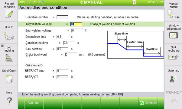
Figure 5.7 welding end condition dialog box (Example of digital EWM)
After changing an item of the welding end condition, if the [ESC] key is pressed, the screen will move to the welding start condition dialogue box without saving the changed content. If the [F7: Complete] key is pressed, the changed content will be saved and the screen will move to the welding start condition dialogue box.
The ‘FTT level adjust’ of the end condition can be used only for GB2/GZ4/GE2, while other items can be commonly used for welders.
The contents of individual items are as shown below.
(1) Condition number: [ 1] (Range: cannot change)
Display the welding start condition number. In case of the digital arc welding function, the end condition number and the start condition number are managed together as one. Accordingly, in order to change the end condition number, the start condition number needs to be changed. In the end condition screen, checking is allowed only, while changing is not.
(2) End welding current / Welding power / Feeding speed
| Name | Unit | Range | Default |
HRWI GB2/GZ4/GE2 MEGMEET | End welding current | % | 10 ~ 100 | 70 |
Fronius | End welding power | % | 10 ~ 100 | 70 |
ESAB | End feeding speed | % | 10 ~ 100 | 70 |
EWM | End feeding speed | m/min | 0.0~25.0 | 7.0 |
Set the current value that will be outputted when handling craters. Set the % amount against the main condition (Welding current, welding power, and feeding speed of the start condition). However, For EWM welders, set the same ‘m/min’ as the mainl condition,
(3) End welding voltage correction / Arc length correction
| Name | Unit | Range | Default |
HRWI | End welding voltage correction | % | 50.0 ~ 150.0 | 100 |
GB2/GZ4/GE2 ESAB/EWM | End welding voltage correction | V | -10.0 ~ 10.0 | 0 |
Fronius | End arc length correction | % | -30.0 ~ 30.0 | 0 |
Set the voltage (arc length) correction value when handling craters. It is necessary to set the voltage that needs to be outputted.
(4) Down Slope time (Crate Time): [ 0.10] sec (Range : 0.0 ~ 10.0)
Set the time for processing the current change between the main condition and the end condition as a slope.

Figure 5.8 DownSlope time and crate time chart
(5) End condition time: [ 1] sec (Range : 0.1 ~ 10.0)
Set the time for maintaining the output value as set in the ‘current ratio’ item of the welding end condition.
(6) Burnback adjustment: [ 0] % (Range: -20 ~ 20)
Set for processing Burnback.
(7) Gas postflow: [ 0.10] second (Range: 0.3 ~ 10.0)
Set the time for emitting the shied gas continuously even after arc is turned off.
(8) FTT level adjustment (Can be set only for GB2/GZ4/GE2): [ 0] (Range: -50 ~ 50)
Set the Fine tip treatment adjustment value. Through this value, the amount of wire agglomerated at the wire tip, after welding, can be adjusted.
(9) Crater backward distance: [ 0] (Range: 0–100)
Sets the distance for the robot to move backward during the DownSlope time + Condition sustaining time in the middle of the crater handling process; the speed will be determined automatically based on distance and time.
(10) Retract time: [ 0] (Range: 0.0-10.0)
Sets the time for the robot to rewind the wire while performing the next movement after the handling of the welding end process is completed; this will be used to prevent the start of the welding while the wire is bent because of interference, or the wire is in contact when the next step starts.
(11) Retract speed: [ 0] (Range: 0.0-100)
Designates the wire feed speed for rewinding the wire when the welding is finished; the speed will be set as the ratio against the maximum current.
5.5. Welding auxiliary condition - retry
In some cases, the arc cannot be generated due to impurities attached near the welding start point on the base metal. When an arc cannot be ignited, the Retry function will allow a retry of arc ignition, allowing the robot to work continuously without stopping.
While the arc welding is set as digital, if the [F1: Aux. cnd] key on the welding start condition dialogue box is pressed, the welding auxiliary condition editing screen will be displayed as shown below.
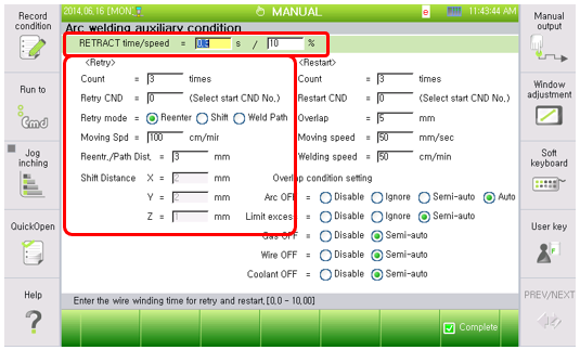
Figure 5.9 Welding auxiliary condition dialog box retry (Digital welders, Retry)

l The retry function is to be performed when trying but keeping failing to turn on the arc. The restart function is to be performed when needed to restart the arc welding after stopping in the middle of welding being performed.
The item displayed on the left side of [Figure 5.7] shows the retry condition of the welding auxiliary conditions. The contents of individual items of the retry condition are as shown below.
(1) Retraction time: [0] second(s) (Range: 0.00 ~ 10.00)
A retrial will take place when the arc is not generated after trying to feed the wire and perform welding. This may cause the wire to be fed excessively when retrying. In this case, the wire and the base metal may be in contact with each other, causing stick or moving the wire too close to the base metal in a way that can cause arc generation instability. In response to the problem, the system provides a function that creates a proper environment for welding by retracting the wire before retrying. This function is used for setting the time of wire retraction. As long as its value is not 0, the wire will be retracted and the torch will move before an arc generation attempt.
(2) Retraction speed: [10] % (Range: 0 ~ 100)
This is used for setting the speed of wire retraction when retrying. The function may not be supported on some welders. (Ex. Saprom welders)
(3) Count: [5] time (Range: 0 ~ 9)
Set the count of retries to be applied when failing to turn on the arc. If failing continuously within the set count, the robot will move back to the home position (The first arc ignition try point, welding start point) and stops there.
(4) Retry condition: [ 0] (Range: 0 ~ 32)
Enter the number of the welding condition to be applied when retrying to turn on the arc. Welding will be performed according to the main condition (Including current and voltage) of the welding start condition as entered for retrying. However, if the entered condition number is “0”and if the operation mode is reentry, the retried welding will be performed according to the main condition of the welding start condition that is being executed currently.
(5) Retry mode: <Reenter, Shift, Weld Path>
Set the method for moving the torch for the retry. 3 setting modes are supported, and individual methods for moving the torch are as shown below depending on their settings. Refer to Figure 5.8
A. Reenter
Retry arc generation after moving back to the previous step in case arc generation is failed. Enter the moving distance to the distance during retracting/moving welding path during the retrial mode. Set the moving distance to ‘Reentr./Path Dist.’ distance in the Welding auxiliary condition retry setting menu. Follow the welding start condition for voltage and current condition since the robot will step forward again after stepping back a certain distance.
B. Shift
The robot will move set shift distance in retry condition of Welding auxiliary condition and return to the arc generation step. The shift distance can be set in the front/rear, left/right, and up/down directions based on the welding line. The welding condition for retrying is the welding start condition in the retry condition item. When an arc is generated successfully, the robot will perform welding after moving to the welding start point at the set speed.
C. Multi-direction
The first try will be made after moving along the welding line as much as the front/rear direction distance among the distances set in the “Shift movement amount” in the retry condition of the welding auxiliary condition. The second try will be performed after moving the distance that considers the distances set in the left/right and up/down directions. In the third try, the welding will be tried only after moving in the opposite direction of the left/right direction of the second try.
In the fourth to sixth tries, the same work as the works done in the first to third tries will be performed but along the distance two times longer. In the seventh to ninth tries, the same work will be performed along the distance three times longer. Welding will start according to the welding start condition of the retry condition item. When the arc generation is successful, the movement to the welding start point will take place at the set speed, while the arc is sustained, and then welding will be progressed.
(6) Moving Speed: [100]cm/min (Range : 1 ~ 999)
It is the speed of torch to move to the retry point or to return to the welding start point.
(7) Retraction movement distance.: [3] mm (Range : 0.00 ~ 99.99)
This is the distance that the torch will move when reentering if the operating mode is set as reentry. The operating mode can be designated in the starting condition.
(8) Shift movement amount: Front/rear=[2], left/right=[2], up/down=[1] mm (Range : -99.9 ~ 99.9) This is the distance that the torch will move if the operating mode is set as shift and multi-direction.
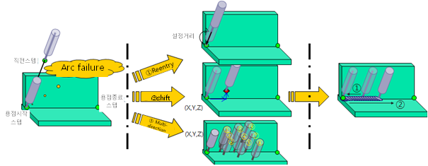
Figure 5.10 Reentry function sequence

5.6. Welding auxiliary condition - restart
While arc welding is in progress, the welding work may be stopped for several reasons, such as arc off, exceeding the welding current and voltage limits, lowering of gas pressure, shortage of wire, and coolant errors. In these cases, if welding restarts from the stopped point, there may be some sections that are not welded. The Restart function is for performing overlapped welding to make up for the sections, which may not have been welded in the process.
The restart condition setting allows a necessary restart after the welding stops in response to some specific reasons, such as arc off. When the welding restarts automatically without taking specific measures after the welding work has ceased or when the welding work restarts after removing the causes of the cessation, the robot moves backwards along the welding path for a certain distance before perfroming welding again. As a result, there will be an overlapped section near the position where the welding had stopped previously due to errors. This function prevents a section from being passed without being welded after restarting following a cessation in welding.
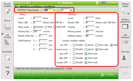
Figure 5.11 Welding auxiliary condition dialog box (Digital welder, Restart)
Wire could be stuck to the base metal when welding is completed. The automatic stick removal condition is for setting a function for allowing stick to be removed automatically.
The content per each item of the automatic stick recovery condition is as follows.
(1) Retraction time: [0] second(s) (Range: 0.00 ~ 10.00)
When the welding is restarted after being stopped, the wire may be fed excessively for many reasons. In this case, the wire and the base metal may be in contact with each other, causing stick or the wire may be too close to the base metal resulting instability of arc generation. Responding to the problem, the system provides a function that creates a proper environment for welding by retracting the wire before retrying. This function is used for setting the time for retracting the wire. As long as its value is not 0, the wire will be retracted and the torch will move before arc generation is attempted.
(2) Retraction speed: [10] % (Range: 0 ~ 100)
This is used for setting the retraction speed of the wire when restarting. The function may not be supported on some welders. (Ex. Saprom welders)
(3) Restart count: [5] time (Range : 0 ~ 9)
Designate the maximum number of times re-operating within same welding period. When this number is exceeded, “E1274 Number of times re-operating within same welding period exceeded” error will occur.
(4) Restart condition: [0] (Range : 0 ~ 32)
Enter the number of welding condition to be applied in the overlap range when restarting. When needed to restart welding by overlapping, welding will be performed in the overlapped range based on the main condition (Including current and voltage) of the welding start condition as entered for restarting. However, if the entered condition number is “0”, welding will be performed according to the main condition of the welding start conditions currently being executed in the overlapped range.
(5) Overlap: [5] mm (Range : 0.0 ~ 99.9)
It is the welding overlap distance (Overlap distance) for restarting welding. The robot will move back the overlap distance and start welding work again.
(6) Moving speed: [50] mm/second (Range: 1~999)
Set the speed at which the torch moves back to the overlap start point. It means the speed of moving in the range of ③ ~ ④ as shown in [Figure 5.10] (Refer to Figure 5.13).
(7) Welding speed: [50] cm/minute (Range: 1~999)
Set the speed at which the robot moves from the overlap start point to the end point while performing overlap. It means the speed of moving along the overlap length starting from ④ as shown in [Figure 5.13] (Refer to Figure 5.13).
When an error occurs while performing welding from the welding start point to the welding end point (⑤), if the overlap condition is semi-automatic, the user needs to identify what have caused welding to stop, and take care of the error. After the cause of the error is eliminated (②), if the user presses the [START] button (③) to restart welding, then, the robot will move to the overlap start point automatically at the speed set at [MOVING SPEED] (④). After moving to the overlap start point, the welder will move, while carrying out welding, along the overlap distance at the speed set at [WELDING SPEED] first and, after that, it will move at the normal speed while performing. However, if an error occurs while performing welding in the overlap area, the welder will restart welding at that point.
(8) Overlap condition setting
The bottom right of Figure 5.11 shows how to set the method for performing overlap if welding stops in the middle of arc welding, due to some reasons, such as arc off(Arc off), limit exceeded, gas off(lowering of gas pressure), wire off(wire shortage) and coolant off(coolant error).
A. Automatic
This setting is used to perform automatic overlap. It can be set only when the welding is stopped by arc off. When the arc is turned off during welding, the robot will not stop. It will instead perform the overlapped welding according to the methods set in the restart options of the welding auxiliary condition before performing the main welding work. However, when the arc is turned off again while performing overlapped welding in the section, it will be restarted at the position without overlapping.
B. Semi-automatic
This setting is used to allow the user to perform the overlapped welding. When events, such as arc off, exceeding of limits, lowering of gas pressure, wire shortage, and coolant errors occur, arc welding and the robot will both come to a halt. When the cause is removed and the user presses the [Start] button, the robot will perform the overlapped welding according to the methods set in the restart options of the welding auxiliary condition before performing the main welding work.
At this point, if the user moves the robot to another position through a jog operation and presses the [Start] button, the robot will move to the overlap welding position and perform welding.
 Caution
While the robot is moving, if the step forward/backward key is pressed, the restart information will be initialized, preventing overlapped welding. Movement must be performed through the jog operation.
C. Ignore
This setting is used to ignore errors. When the setting is activated, the robot will move continuously without stopping after the welding has ceased. This means that even when the arc is turned off or the limits are exceeded, the robot will ignore these events and continue. This operation can be performed only when restarting after the welding has stopped due to arc off or exceeding of limits.
D. Inhibit
This setting is used to prevent overlaps. When events, such as arc off, exceeding of limits, lowering of gas pressure, wire shortage, and coolant errors occur, arc welding and the robot will both come to a halt. When the cause is removed and the user presses the [Start] button, the robot will start and continue welding at the stopped position without performing overlapped welding.
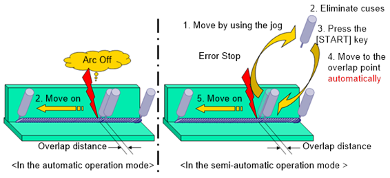
Figure 5.12 Restart operation sequence