5.3. Welding start condition– Execute it by using [Quick Open] at ASF#=x
5.3. Welding start condition– Execute it by using [Quick Open] at ASF#=x
While the arc welding setting is digital, and there is the cursor on the ARCON ASF#= command line, if the [Quick Open] key is pressed, the welding start condition editing screen will be displayed as shown below.
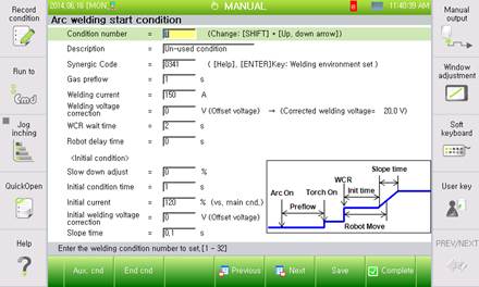
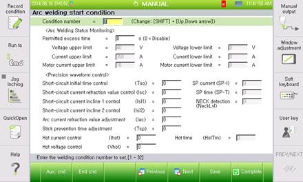
Figure 5.2 Welding start condition dialogue box (Example of GB2 digital welder)
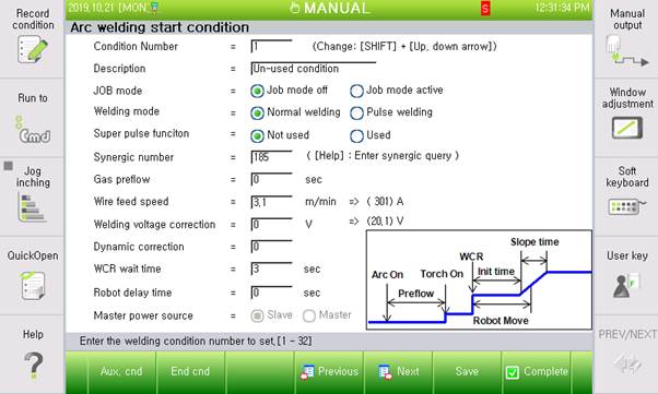
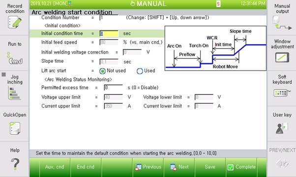
Figure 5.3 EWM welder’s welding start condition dialog box
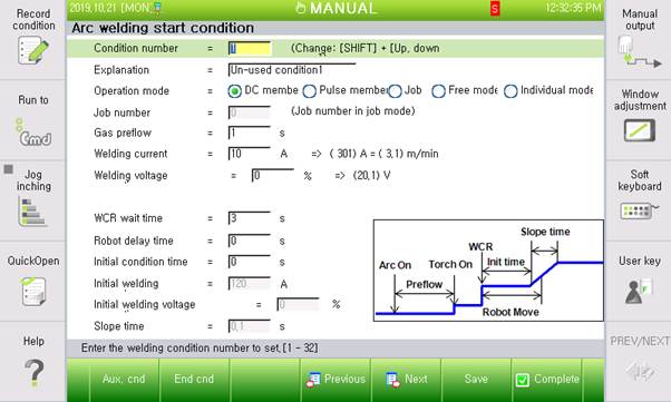
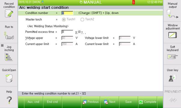
Figure 5.4 Megmeet welder’s welding start condition dialog box
After the conditions are edited, if the [ESC] key is pressed, the dialogue box will close without saving the edited condition. If the [F7: Complete] key is pressed, the edited content will be saved and the dialogue box will close.
The following information is about the items that are to be applied commonly for welders. Refer to [Chapter 4. Arc welder setting] for the items that can be set specifically for individual welders.
The contents of the common items may vary in their model type, units and range. Refer to each table of individual items when it comes to the difference of welders.
(1) Condition number
| Name | Range |
Common to all welders | Condition number | 1 ~ 32 |
Designate the welding start condition number for editing. (32 conditions can be designated and used)
(2) Description
| Name |
Common to all welders | Description |
Record the description about the relevant welding start condition.
(3) Synergic code
| Name | Unit | Range | Default |
HRWI | Synergic code | - | - | 040 |
GB2/GZ4/GE2 | Synergic code | - | - | 0340/1153/0340 |
ESAB, Fronius MEGMEET | Not supported | |||
EWM | JOB Nr.(synergic) | - | - | 185 |
Set the synergic code that needs to be sent to the welder. The code value can be set through the synergic code selection dialogue box. It is possible to enter the synergic code selection dialogue box by pressing the [Help] key, or pressing the [Enter] key when the cursor is placed on the welding environment code.
(4) Gas preflow (When controlling the gas signal)
| Name | Unit | Range | Default |
Common to all welders | Gas preflow | Second | 0.0 ~ 10.0 | 0.5 |
Set the time for emitting the shield gas in order to separate the welding area from the atmosphere before starting welding.
(5) Welding current/ Welding power / Feeding speed
| Name | Unit | Range | Default |
HRWI | Welding current | A | 0.0 ~ 500.0 | 100 |
GB2/GZ4/GE2 | Welding current | A | 30.0 ~ 350.0 | 150 |
Fronius | Welding power | % | 0.0 ~ 100.0 | 10 |
ESAB/EWM | Wire feeding speed | m/min | 0.0 ~ 25.0 | 3.1 |
MEGMEET | Welding current | A | 30 ~ 400 | 150 |
Set the value that corresponds to the welding current. This is for the current that will be used for the main conditional welding, while the current to be used for the initial condition as well as the end condition will be decided based on the ratio of this value.
(6) Welding voltage correction/ Arc length correction
| Name | Unit | Range | Default |
HRWI | Welding voltage correction | % | 50.0 ~ 150.0 | 100 |
GB2/GZ4/GE2 ESAB/EWM | Welding voltage correction | V | -10.0 ~ 10.0 | 0 |
Fronius | Arc length correction | % | -30.0 ~ 30.0 | 0 |
MEGMEET | Welding voltage correction | % | -30.0 ~ 30.0 | 0 |
When it comes to digital welding, the welding voltage selected due to the welding current from the synergic data will be used in many cases, the welding voltage will not be entered directly. If needed to change the welding voltage selected automatically due to the synergic data, it is required to set the offset value for the target voltage based on the relevant welding voltage.
(7) WCR wait time
| Name | Unit | Range | Default |
Common to all welders | WCR wait time | Second | 0.0 ~ 10.0 | 2 |
Displays the WCR input wait time. If the WCR signal is not fed within the time, retry will be performed. However, if the count of retry is 0, an error will be generated and the robot will stop. The functions related to retry, such as restart methods and retry count, can be set from the welding auxiliary condition (Refer to 5.5. Welding auxiliary condition – retry and 5.6. Welding auxiliary condition - restart).
(8) Robot delay time
| Name | Unit | Range | Default |
Common to all welders | Robot delay time | Second | 0.0 ~ 10.0 | 0 |
Set the wait time before the robot performs welding by following the welding path after the arc welding gets started normally. It has nothing to do with the initial condition and the robot can move while the initial condition is being processed.
(9) Initial condition time
| Name | Unit | Range |
Common to all welders | Initial condition time | Second | 0.0 ~ 10.0 |
Set the time for maintaining the initial current value when welding gets started.
(10) Initial welding current / Welding power / Feeding speed
| Name | Unit | Range | Default |
HRWI GB2/GZ4/GE2 MEGMEET | Initial welding current | % | 20 ~ 200 | 120 |
Fronius | Initial welding power | % | 20 ~ 200 | 120 |
ESAB/EWM | Initial feeding speed | % | 20 ~ 200 | 120 |
Set the output welding current during the initial condition hold time when starting arc welding. Set it based on the % against the welding current of the main condition.
(11) Initial welding voltage correction / Arc length correction
| Name | Unit | Range | Default |
HRWI | Initial welding voltage correction | % | 50.0 ~ 150.0 | 100 |
GB2/GZ4/GE2 ESAB/EWM | Initial welding voltage correction | V | -10.0 ~ 10.0 | 0 |
MEGMEET | Initial welding voltage correction | % | -30.0 ~ 30.0 | 0 |
Fronius | Initial arc length correction | % | -30.0 ~ 30.0 | 0 |
Set the output welding voltage during the initial condition hold time when starting arc welding. Set it based on the corrected value against the synergic voltage.
(12) Slope time
| Name | Unit | Range |
Common to all welders | Slope time | Second | 0.0 ~ 10.0 |
Set the time for processing the change of current between the initial condition and the main condition as a slope.
(13) Permitted excess time
| Name | Unit | Range | Default |
Common to all welders | Permitted excess time | Second | 0.0 ~ 10.0 | 0 |
Set the allowable limit exceeded time for the welding current/voltage and the feed motor current. If the welding current/voltage or the feed motor exceeds the limit for longer than this time limit, restart will be performed. However, if the count of retry is 0, an error will be generated and the robot will stop. The functions related to retry, such as restart methods and retry count, can be set from the welding auxiliary condition (Refer to 5.6 Welding auxiliary condition – restart). If the time is set as 0, the arc limit monitoring function will not be used.
(14) Voltage upper limit/voltage lower limit
| Name | Unit | Range |
Common to all welders | Voltage upper limit /Voltage lower limit | V | 0.0 ~ 100.0 |
Set the upper and lower voltage limits to be applied while carrying out welding. An error will be generated when the limit is exceeded for longer than allowable time.
(15) Current upper limit/current lower limit
| Name | Unit | Range |
Common to all welders | Current upper limit/ Current lower limit | A | 0 ~ 1000 |
Set the upper and lower current limits to be applied while carrying out welding. An error will be generated when the limit is exceeded for longer than allowable time.
(16) Motor current upper limit/Motor current lower limit
| Name | Unit | Range | Default |
GB2/GZ4 | Motor current upper limit/ Motor current lower limit | A | 0.0 ~ 50.0 | 10/0 |
Other welders | Not supported | |||
Set the motor upper and lower current limits to be applied while carrying out welding. An error will be generated when the limit is exceeded for longer than allowable time.
5.3.1. Welding start condition– Exclusive setting for HRWI
5.3.2. Welding start condition - Exclusive setting forGB2/GZ4/GE2
5.3.3. Pulse welding condition– Exclusive setting for GE2
5.3.4. Welding start condition– Exclusive setting for Fronius
5.3.5. Welding start condition– Exclusive setting for ESAB
5.3.6. Welding start condition– Exclusive setting for EWM
5.3.7. welding start condition– Exclusive setting for Megmeet