4.2. HRWI characteristic file editing
4.2. HRWI characteristic file editing
(1) Communication method
It sets the method to communicate with the Hyosung welder.
The Hyosung welder supports CAN communication, while DeviceNet communication can be used depending on the site situation.
After removing the welder cover, you can set the welder communication through the dip switch on the main board.
The following shows how you can set the communication in the Zi-sol model.
n Turn off the welder, and then change the setting of dip switch no. 1 (SW1). After that, turn on the power.
n The part marked in light color in the figure below is the protruding part of the dip switch.

(2) CAN communication speed: {125kbps, 250kbps, 500kbps, 1Mbps}
Set the communication speed of a welder. It is required to check the communication speed that is supported by the welder.
For Hyosung welder, the communication speed should be set to 250 kbps.
(3) CAN communication port: {CAN port 1, CAN port 2, CAN port 3}
This sets the CAN port used for communicating with the welder. As one of the 4 CAN ports has been already used basically, one of the remaining 3 ports needs to be designated for the use.
CAN port 1: When BD5B2 or the DeviceNet connector on the controller door is used
CAN port 2: When the BD574 DeviceNet connector is used
CAN port 3: Smaller connector in the case of using the BD574 two-port model
(4) Input setting start port
The set port will be used as a reference port that will become the starting point among the input ports during the automatic assignment.
(5) Output setting start port
The set port will be used as a reference port that will become the starting point among the output ports during the automatic assignment.
(6) Port setting
When using the DeviceNet interface, if you press the [F1: Port Setting] key, you can enter the dialog box to set the input/output signal port.
(7) Automatic assignment
When using the DeviceNet interface, if you press the [F2: Auto Assignment] key, the input/output signals will be automatically assigned based on the input and output setting start ports set above. After that, you will be automatically allowed to enter the port setting dialog box.
(8) Port setting dialog box
If you press the “port setting” or “auto assignment” button, you can enter the input or output port setting dialog box, as shown below.
If ports will not be used, set them to “0,” allowing the internal processes associated with those signals to be skipped. It is recommended to use the set values for individual ports.
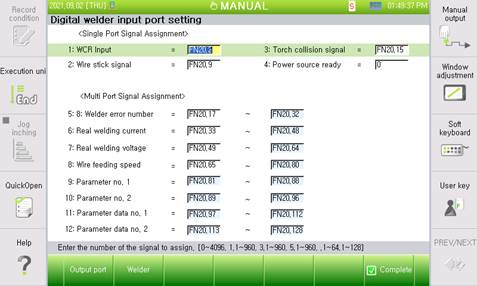
Figure 4.4 Welder input port setting dialog box (when Hyosung welder is used)
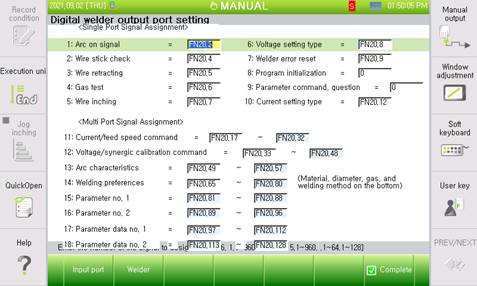
Figure 4.5 Welder output port setting dialog box (when Hyosung welder is used)