1.1. System configuration
1.1. System configuration
The following figure shows the general configurations of the synchronization systems for conveyors and presses.
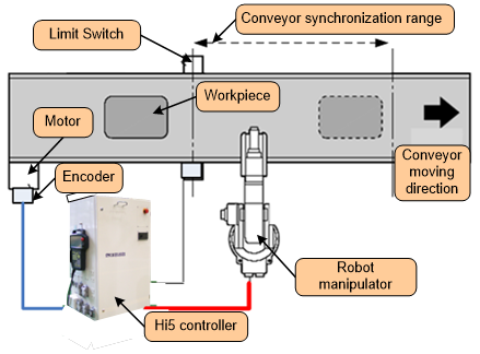
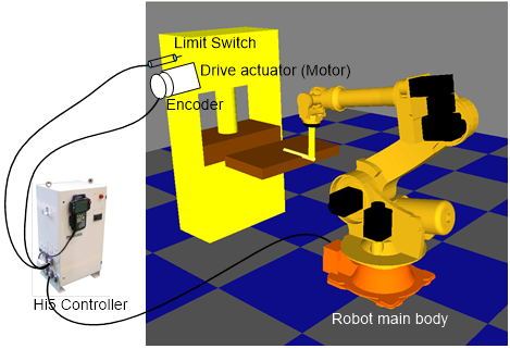
n Limit switch
This unit is for providing the controller with the information that a workpiece is entering a specific position on the conveyor or passing a specific position on a press. The position of the limit switch is a reference point for determining a position.
n Encoder
The motor drive part is connected with an encoder that generates pulses equivalent to the amount of the rotation of the motor. The encoder is connected with the robot controller to feed the pulses generated from the encoder into the robot controller.