6.3. Using in embedded PLC
6.3. Using in embedded PLC
[Figure 6.1] is the block diagram of the embedded PLC I/O, including the FB channel.
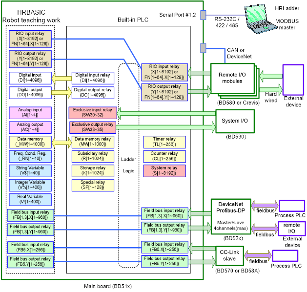
Figure 6.1 Block diagram of embedded PLC I/O
[Figure 6.2] shows an example of an embedded PLC connection. 4 words are connected to both Input and Output.
“DOW13 ~ DOW16” output of robot language is mapped to “FB2.YW1 ~ FB2.YW4” output of Fieldbus.
“FB2.XW1 ~ FB2.XW4” input of Fieldbus is mapped to “DIW13 ~ DIW16” input of robot language.

Figure 6.2 Example of embedded PLC ladder with robot language input and output mapping on Fieldbus