3.2. Additional axis constant setting
3.2. Additional axis constant setting
(1) Select 『[F2]: System』 → 『5: Initialize』 → 『5: Additional axis constant』from the menu in manual mode.
(2) Set the additional axis constant.
(3) To save the set data, press the『[F7]: Complete』key.
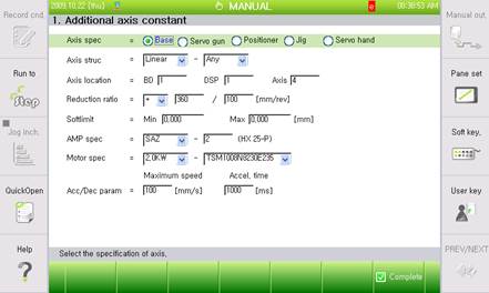
◆ 【Additional axis constant】 ◆
(1) Axis specification:
Select an additional axis type from <base, servo gun, positioner, jig, servo hand>.
When deciding an additional axis specification, the order of [base → servo gun → positioner → jig → servo hand] should be observed, according to the logical order of the additional axis.
(2) Axis configuration: Select the operating form and direction of the axis.
Select <X> for front/rear axis movement, <Y> for left/right axis movement and <Z> for up/down axis movement when using a translation base axis (drive axis). Select <Optional> and execute 『Base axis calibration』 if the base axis is not installed in the same direction as the robot coordinate system. Select Rx/Ry/Rz or <Optional> and execute 『Base axis calibration』 for a rotation base axis, in the same manner as for translation base axis. Refer to 『Spot welding function manual』 if setting servo gun, and 『Positioner synchronization function manual』if using positioner.
(3) Axis location: Assign mechanical configuration of additional axis to be used by user.
BD =[1](1~2) => Assign BD542 board No. (2DSP/1Board)
DSP =[1](1~2) => Assign DSP No. inside of DSP BD542 board. (4Axis/1DSP)
Axis =[4](1~4) => Assign axis No.
Ex.) If assigning as 1,1,4 for setting additional axis No. 6…
Basic axis 6 axes – main 3 axes (BD542 No. 1, DSP No. 1, 1~3 axes)
3 wrist axes (BD542 No. 1, DSP No. 2, 1~3 axes)
Additional 1 axis (BD542 No. 1, DSP No. 1, axis No. 4)
(4) Reduction ratio: Register the moving distance of the axis per motor rotation.
Register the moving distance of axis per number of motor rotations in mm, and the rotation angle of the axis per motor rotation in degrees for translation axis. Set “+” for symbol if the grid value of the additional axis is increased, and “-“ for symbol if the grid value of the additional axis is decreased, since the forward direction of the motor (direction of encoder is increased) conforms to the direction of axis motion. Please refer to the following examples.
Ex. 1) For a rotation axis using 1/100 reduction gear only…
Axis rotates 360 degrees with 100 rotations of the motor,
Reduction ratio = + 360 / 100 [deg/rev]
Ex. 2) For a translation axis using 1/20 reduction gear and PCD 110mm rack and pinion…
Axis moves 110xPhi (=3.14159)=345.5749[mm] with 20 motor rotations
Reduction ratio = + 3455749 /200000 [mm/rev]
Ex. 3) For a translation axis using 1/5 reduction gear and Lead 5mm ball screw…
Axis moves 5 mm with 5 motor rotations
Reduction ratio = + 5 / 5 [mm/rev]
(5) Soft limit: Set valid moving zone of robot (Soft limit of additional axis).
If setting translation axis in [mm] and rotation axis in [degrees], setting values will be reflected in 『[F2]: System』 → 『3: Robot parameter』 → 『3: Soft limit』.
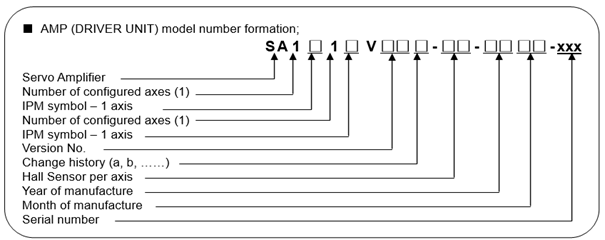
(6) AMP specification: Select the AMP specification to be used for the additional axis.
Select the AMP specification by selecting the IPM signal form and inputting Hall Sensor specification as a number from 0 to 5. The form specification of AMP is as follows.
The following rated capacity will be given according to IPM symbols and Hall Sensor symbols.
AMP Model | IPM symbols | IPM Current rate | Hall Sensor | Full Scale current | |
Large | L | 150Apeak | 0 | 140.62Apeak | |
1 | 93.75Apeak | ||||
X | 100Apeak | ||||
2 | 46.87Apeak | ||||
Y | 75Apeak | 3 | 28.12Apeak | ||
4 | 18.75Apeak | ||||
Z | 50Apeak | ||||
5 | 9.37Apeak | ||||
Small | A | 30Apeak | 3 | 28.12Apeak | |
4 | 18.75Apeak | ||||
D | 10Apeak | ||||
5 | 9.37Apeak |
(7) Motor specification: Select the motor specification used for additional axis.
Select motor capacity first, and then select motor specification.
(8) Acceleration and deceleration parameter: Set the maximum speed and acceleration time of the additional axis.
These setting values will be applied in the same manner as the setting values of 『[F2]: System』 → 『3: Robot parameter』 → 『34: Accel and decel parameter』. The maximum speed of the additional axis is assigned by the user, and is restricted according to the rated speed of motor.
If vibration occurs during the operation of an additional axis, acceleration time should be adjusted.