5.6.2.2. Digital Output
5.6.2.2. Digital Output
Two-way output at 32 points using MOSFET is provided for the digital output. The user can output each 16-point signal through the connector and terminal as required, and the 8-point output is the relay contact point output.
(1) Output through terminal block
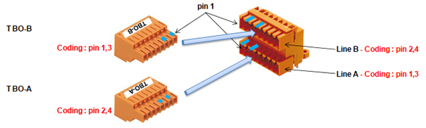
Figure 5.38 Digital Output Terminal Block TBO of LDIO Board (BD58A)
Table 5‑14 Terminal Configuration of the Digital Output Terminal Block TBO of the LDIO Board (BD58A)
Terminal Block Name | Terminal Number | Signal Name | Function Description |
TBO - A | 1 | P2 | Power output: DC24V |
2 | OUT11 | Digital output 11 (Relay contact point output) | |
3 | OUT12 | Digital output 12 (Relay contact point output) | |
4 | OUT13 | Digital output 13 (Relay contact point output) | |
5 | OUT14 | Digital output 14 (Relay contact point output) | |
6 | OUT15 | Digital output 15 (Relay contact point output) | |
7 | OUT16 | Digital output 16 (Relay contact point output) | |
8 | OUT17 | Digital output 17 (Relay contact point output) | |
9 | OUT18 | Digital output 18 (Relay contact point output) | |
10 | M2 | Power output: DC24V GND | |
TBO - B | 1 | P2 | Power output: DC24V |
2 | OUT21 | Digital output 21 | |
3 | OUT22 | Digital output 22 | |
4 | OUT23 | Digital output 23 | |
5 | OUT24 | Digital output 24 | |
6 | OUT25 | Digital output 25 | |
7 | OUT26 | Digital output 26 | |
8 | OUT27 | Digital output 27 | |
9 | OUT28 | Digital output 28 | |
10 | M2 | Power output: DC24V GND |
The versions of BD58AV20 board and over have changed the output from the 8-point relay contact provided by BD58AV10 to the N channel FET.
Table 5-15 Terminal Block TBO Terminal Composition of the Digital Output for Each Version of the LDIO Board (BD58A)
Board Name | Name Of Terminal Block | Terminal No. | Signal Name | Function |
Common | TBO - A | 1 | P2 | Power Output: DC24V |
BD58AV10 | 2~9 | OUT11~18 | Digital Output 11~18 (Output Of Relay Contact) | |
Versions of BD58AV20 and Over | Digital Output 11~18 (Output Of N Channel FET) | |||
Common | 10 | M2 | Power Output: DC24V GND |
(2) Output through connector
The following Figure and Table show the pin composition of the connector CNO for digital output.
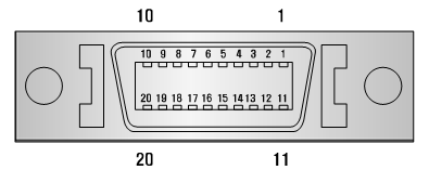
(a) Board side (3M MDR 10220-52A2JL)
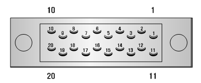
(b) Plug side 3M MDR 10120-3000VE (HOOD: 10320-52F0-008)
Figure 5.39 CNO Connector of LDIO Board (BD58A)
Table 5‑16 Pin Configuration of the Digital Input Connector CNO of the LDIO Board (BD58A)
Pin Number | Signal Name | Function Description |
1 | OUT31 | Digital output 31 |
2 | OUT32 | Digital output 32 |
3 | OUT33 | Digital output 33 |
4 | OUT34 | Digital output 34 |
5 | OUT35 | Digital output 35 |
6 | OUT36 | Digital output 36 |
7 | OUT37 | Digital output 37 |
8 | OUT38 | Digital output 38 |
9 | M2 | Power output: DC24V GND |
10 | P2 | Power output: DC24V |
11 | IN41 | Digital input 41 |
12 | IN42 | Digital input 42 |
13 | IN43 | Digital input 43 |
14 | IN44 | Digital input 44 |
15 | IN45 | Digital input 45 |
16 | IN46 | Digital input 46 |
17 | IN47 | Digital input 47 |
18 | IN48 | Digital input 48 |
19 | M2 | Power output: DC24V GND |
20 | P2 | Power output: DC24V |
The output specifications using photo MOSFET are as follows.
l Output component: Photo MOSFET output
l Rated output = 125 mA (Continuous load current), 24V DC
The relay contact output specifications are as follows:
l Output element: relay contact output
l Rated output = 5A/24VDC, 5A/250VAC
The FET output specifications of the versions of BD58AV20 and over are as follows:
l Output element: N channel FET output
l Rated output = 1A/24VDC
The user connects the output signal as shown in Figures 5.40, 5.41 and 5.42 below.

Figure 5.40 Method for Wiring the Output Signal of LDIO Board (BD58A) (Photo MOSFET)
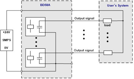
Figure 5.41 Method for Wiring the Output Signal of LDIO Board (BD58A) (Relay Contact Point)
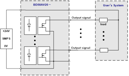
Figure 5.42 How to Connect the FET Output Signal with the Versions of the LDIO Board BD58AV20 and Over.