5.6.2.1. Digital Input
5.6.2.1. Digital Input
The photocoupler is used for digital input, and a total of 32 points are provided. The user can input each 16-point signal through the connector and terminal as required.
(1) Input through connector
The following Figure and Table show the pin composition of connector CN1 for digital input.
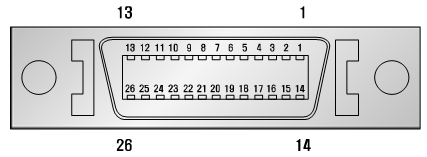
(a) Board side (3M MDR 10226-52A2JL)
(b) Plug side 3M MDR 10126-3000VE (HOOD: 10326-52F0-008)
Figure 5.35 Digital Input Connector CNI of LDIO Board (BD58A)
Table 5‑12 Pin Configuration of the Digital Input Connector CNI of the LDIO Board (BD58A)
Pin Number | Signal Name | Function Description |
1 | IN11 | Digital input 11 |
2 | IN12 | Digital input 12 |
3 | IN13 | Digital input 13 |
4 | IN14 | Digital input 14 |
5 | IN15 | Digital input 15 |
6 | IN16 | Digital input 16 |
7 | IN17 | Digital input 17 |
8 | IN18 | Digital input 18 |
9 | M2 | Power output: DC24V GND |
10 | ||
11 | P2 | Power output: DC24V |
12 | ||
13 | ||
14 | IN21 | Digital input 21 |
15 | IN22 | Digital input 22 |
16 | IN23 | Digital input 23 |
17 | IN24 | Digital input 24 |
18 | IN25 | Digital input 25 |
19 | IN26 | Digital input 26 |
20 | IN27 | Digital input 27 |
21 | IN28 | Digital input 28 |
22 | M1 | Power output: DC24V GND |
23 | ||
24 | P1 | Power output: DC24V |
25 | ||
26 |
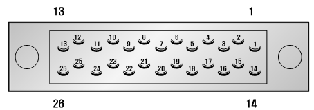
(2) Input through terminal block
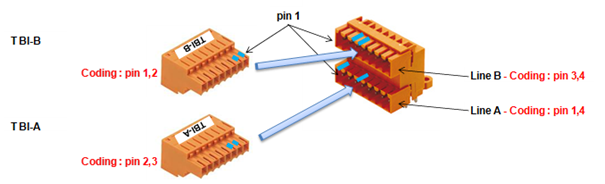
Figure 5.36 Digital Input Terminal Block TBI of LDIO Board (BD58A)
Table 5‑13 Terminal Configuration of the Digital Input Terminal Block TBI of the LDIO Board (BD58A)
Terminal Block Name | Terminal Number | Signal Name | Function Description |
TBI - A | 1 | P2 | Power output: DC24V |
2 | IN31 | Digital input 31 | |
3 | IN32 | Digital input 32 | |
4 | IN33 | Digital input 33 | |
5 | IN34 | Digital input 34 | |
6 | IN35 | Digital input 35 | |
7 | IN36 | Digital input 36 | |
8 | IN37 | Digital input 37 | |
9 | IN38 | Digital input 38 | |
10 | M2 | Power output: DC24V GND | |
TBI - B | 1 | P2 | Power output: DC24V |
2 | IN41 | Digital input 41 | |
3 | IN42 | Digital input 42 | |
4 | IN43 | Digital input 43 | |
5 | IN44 | Digital input 44 | |
6 | IN45 | Digital input 45 | |
7 | IN46 | Digital input 46 | |
8 | IN47 | Digital input 47 | |
9 | IN48 | Digital input 48 | |
10 | M2 | Power output: DC24V GND |
The input specification of each port is as follows.
l Input port component: AC input photo coupler
l Input impedance= 3 ㏀
l (+) Common input voltage = 24 VDC
l (-) Common input voltage = 0 VDC
The user connects the input signal through the method shown in Figure 5.34 below.
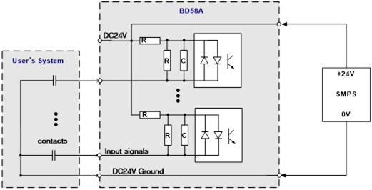
Figure 5.37 Method for Wiring the Input Signal of LDIO Board (BD58A)