5.4.2.3. CAN Communications Connector CANS1, CANS2
5.4.2.3. CAN Communications Connector: CANS1, CANS2
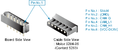
Figure 5.23 Method for the Connection of the CAN Connector of the CC-LINK Board (BD570)
For the CAN Communications Connector, there are two identical connectors with the same pin specification, which are installed as shown in Figure 5.22 above. As CAN communication is conducted through cable, with a Daisy Chaining method, it therefore does not matter which side of the connector it is connected to, as it does not affect the operation.
When the board is installed in the terminal of the CAN communication system, the terminal shall be handled according to the following methods.
Table 5-9 How to Deal with the Can Communication Terminal of the CC-link Board (BD570)
Board Type | Terminating Equipment | Form | How To Set | Set During Forwarding | |
Terminal | Non-Terminal | ||||
BD570V10 | Jumper JP1 |
|
|
|
|
SHORT | OPEN | SHORT | |||
BD570V20 | Dip switch DSW2 |
|
|
|
|
ALL ON | ALL OFF | ALL ON | |||


