5.4.3. Indication and Setting Units
5.4.3. Indication and Setting Units
Various LEDs are used to display the communication status of the CC-LINK line. Indicated details of each LED are displayed on the board, as shown in Figure 5.23 below. You may also use the dip switch to set the number and communication speed of the CC-LINK board; relevant details are indicated on the board shown in Figures 5.24 and 5.25 below.
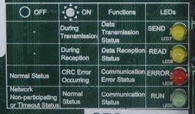
Figure 5.24 LED and Detail of Communication Status Indication of CC-LINK Board (BD570)
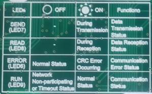

Figure 5. 25 Led For Displaying the Communication Conditions of the CC-link Board (Bd570v20) and the Information
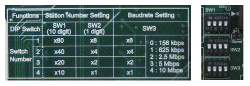
Figure 5.26 Setting Station Number and Communication Speed of the CC-LINK Board (BD570)
Table 5-10 How to Set the CC-link Station Numbers and the Data Rate
Switch Name | Use | Form | How To Set | Set During Forwarding |
Sw1 | Station No. (10 Units) |
| Setting Station Number= (Set Value Of Swz1 X 10) + Set Value Of Swz2 | “0” |
Sw2 | Station No. (1 Unit) |
| “1” | |
Sw3 | Data Rate |
| 0 : 125 Kbps 1 : 625 Kbps 2 : 2.5 Mbps 3 : 5.0 Mbps 4 : 10 Mbps | “4” |


Figure 5.27 Method for Setting of the Number of Stations of the CC-LINK Board (BD570)
Table 5-11 How to Set the Number of the CC-link Station Occupied By the CC-link Board (Bd570v20)
Switch Name | Form | Switch No. | How To Set The No. Of Station Occupied | Set During Forwarding | |||
1 | 2 | 3 | 4 | ||||
SENYU |
| 2 (Senyu1) | Off | Off | On | On | On |
1 (SENYU0) | OFF | ON | OFF | ON | ON | ||
